Copyright © 2015-2021 Peter Popovec <popovec.peter@gmail.com>
Introduction
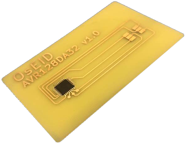
OsEID is amateur/hobby smart card with [RSA] and [EC] cryptography support. It is designed on low cost and easily accessible microcontroller Microchip AVR128DA32 or ATMEGA128.
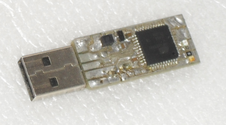
OsEID token is amateur/hobby USB token based on Microchip/Atmel xmega128a4u microcontroller. This projects implements USB reader ([CCID] class) with built in OsEID card.
Project website
OsEID projects releases can be found at at https://oseid.sourceforge.io or https://sourceforge.net/projects/oseid/
Features
-
Open source code (ASM and C)
-
OsEID card - simple mechanical construction, only one integrated circuit!
-
OsEID token - single sided PCB, only 15 components
-
Based on easily accessible microcontroller Microchip AVR128DA / xmega128A4U
-
ISO 7816 compatible note:[Not all ISO specifications are respected, for example, card thickness cannot be accomplished.]
-
support for A,B and C class (ISO7816-3, operating voltage 1.8, 3.3 and 5V)
-
Support for pkcs#15 structure
-
RSA cryptography with side channel attack protection (key size 512 up to 2048 bits)
-
onboard key generation
-
-
Elliptic cryptography with side channel attack protection
-
[ECDSA] operation
-
[ECDH] operation
-
onboard key generation
-
nistp192/prime192v1/secp192r1 [OID] 1.2.840.10045.3.1.1
-
nistp256/prime256v1/secp256r1 [OID] 1.2.840.10045.3.1.7
-
secp384r1 [OID] 1.3.132.0.34
-
secp521r1 [OID] 1.3.132.0.35
-
secp256k1 [OID] 1.3.132.0.10, experimental support, OpenSC patch required
-
-
symmetric cryptography: DES, 3DES, AES 128, AES 192, AES 256
-
Onboard random number generator
-
64 kbyte file space (for keys /certificates etc.)
-
auto size [DF]
-
Supported in Linux/Windows by OpenSC package - MyEID driver
-
Support for T0 and T1 protocol
-
OsEID card: Communication speed 312500 bits/s for 5MHz readers
-
OsEID token: no special card reader driver needed for Linux/WIN/MAC
Drawbacks
-
No Warranty, use at your own risk.
-
It is not possible to buy it, you have to make it.
-
Documentation is still in the form of draft.
-
RSA operations for keys > 1024 is slow
-
about 10.7 seconds for 2048 bit key / token about 10 seconds,
-
about 5.3 seconds for 1536 bit key / token about 4.9 seconds,
-
about 1.8 seconds for 1024 bit key / token about 1.7 seconds,
-
-
RSA key generation is really slow
-
EC operations for keys > 256 is slow, ECDSA operation timing:
-
secp521r1 about 4.8 seconds / token about 4.4 seconds
-
secp384r1 about 2.6 seconds / token about 2.3 seconds
-
prime256v1 about 1.2 seconds / token about 1.1 seconds
-
prime192v1 below 0.6 second / token below 0.5 second
-
secp256k1 about 2.1 seconds / token about 2 seconds
-
-
not perfect constant time EC operations
-
OsEID card - ESD (electrostatic discharge) protection implemented only on token
OsEID - MyEID differences
OsEID tries to support all features which are available in commercial card [MyEID]. Thanks to that, no special software/drivers is needed for commonly used operating systems. For Windows, Linux and Mac OS opensource project [OpenSC] can be used as driver for OsEID card.
OsEID disadvantages to MyEID card (mechanical)
-
no mini SIM version of card
-
mechanical construction - big, not compact as one plastic card
OsEID disadvantages to MyEID card applet version 4.X:
(These functionalities are not supported by MyEID driver in OpenSC up to 0.18, perhaps OsEID will support these functions in future)
-
RSA - only value 65537 is allowed as public exponent
-
experimental support for symmetric encrypt/decrypt - DES and AES
-
experimental support for key unwrap
-
experimental support for key wrap
-
experimental challenge response PIN
-
experimental Admin state and Global unblocker state
-
no PIV/CIV emulation
-
no Auto size files (only auto size DF)
-
no 224 bit NIST curve
-
no support for automatic delete of session objects (please read MyEID 2.3.0 reference manual)
-
slow RSA
-
MyEID applet version 4.5.X allow use RSA keys up to 4096 bits, OsEID maximum is 2048 bits for RSA, and there is no way to run RSA with longer keys in this hardware.
experimental = feature is supported by OsEID card, but original MyEID card function can work differently. There is no enough information in MyEID applet reference manual 2.1.4/2/2.3.0 and no OpenSC implementation to test all functions.
OsEID disadvantages to MyEID card, applet version below 3.5:
(MyEID in version below 3.5 does not support EC cryptography)
-
slow RSA for keys with modulus length over 1024 bits
For a comparison, here is table showing the execution time of RSA decrypt operation (time in seconds) for MyEID cards, and OsEID card/token (with exponent blinding turned on):
pkcs11-tool --decrypt --slot 1 -m RSA-PKCS ..
| key size | 512 | 768 | 1024 | 1536 | 2048 |
|---|---|---|---|---|---|
OsEID card (5 keys) |
2.7 |
3.0 |
3.9 |
7.4 |
12.7 |
OsEID token (5 keys) |
1.2 |
1.4 |
2.3 |
5.5 |
10.6 |
MyEID (3.3.3) (1 key) |
- |
- |
2.7 |
- |
- |
MyEID (4.0.1) (2 keys) |
- |
- |
3.8 |
- |
- |
MyEID (3.3.3) (5 keys) |
3.4 |
3.4 |
3.4 |
3.6 |
3.8 |
MyEID (4.0.1) (12 keys) |
4.2 |
4.2 |
4.3 |
4.4 |
4.7 |
Times in this table are higher then times given in Features section, because here the time is summary of all operations that OpenSC runs on card, e.g. card identification, reading PKCS#15 files, reading public key.
MyEID (3.3.3) card seems to be slower in filesystem operations, listing all card objects by pkcs15-tool -D command run in 2.8 second for 5 RSA keys on card. OsEID card runs the same command, the same set of keys in 1.9 second. If only one key is installed in MyEID card, pkcs15-tool -D command need 2.5 seconds, but OsEID card/token need only 0.7/0.6 sec.
Time depends on card reader, USB utilization etc.
-
ECC speed is comparable to MyEID
MyEID with two keys installed, OsEID with four keys installed. Both cards allow the same communication speed - 312500 bits/s for 5MHz readers, for tests 4.8 MHz reader was used (opensc 0.21.0)
| key size | 192 | 256 | 192 | 256 | 192 | 256 |
|---|---|---|---|---|---|---|
pkcs15-crypt |
pkcs11-tool |
raw |
||||
MyEID (4.0.1) |
1.2 |
1.6 |
1.3 |
3.3 |
0.16 |
0.26 |
OsEID card |
1.4 |
2.2 |
2.3 |
3.0 |
0.55 |
1.2 |
OsEID token |
0.7 |
1.3 |
1.1 |
1.7 |
0.46 |
1.1 |
As You can see, raw time is significant better for MyEID card, but whole ECC operation time is comparable for MyEID and OsEID card.
There is no support for secp384r1 and secp521r1 in MyEID 4.0.1 card. OsEID card/token results:
| key size | 384 | 521 | 384 | 521 | 384 | 521 |
|---|---|---|---|---|---|---|
pkcs15-crypt |
pkcs11-tool |
raw |
||||
OsEID card |
3.2 |
5.4 |
3.7 |
5.9 |
2.6 |
4.8 |
OsEID token |
2.5 |
4.6 |
3.0 |
5.0 |
2.3 |
4.4 |
|
|
raw measurement - the starting time of the measurement is before sending the PERFORM SECURITY OPERATION APDU to the card and the end time of the measurement is the GET RESPONSE operation after receiving the response. (Token uses the T1 protocol, here GET RESPONSE APDU is not used) |
OsEID benefits to MyEID card:
-
secp256k1 curve
-
open source - can be reprogrammed for different usage
-
for people who don’t trust commercial solutions because of backdoors
-
for people who are happy to make a card by themselves
-
card and reader simulation (without real card/reader)
-
AES192 (MyEID reference manual 2.1.4 documents only AES128 and AES256)
Disclaimer
Whole project is published in good faith and is to be used for educational purposes only, however, amateur/hobby usage is also possible. When you decide to use this project in other way, keep in mind all drawbacks. Particularly take care that the card may be damaged and you may lose access to devices, that need authentication with card. Please, consider creating backup card/backup access for this situation. AUTHOR IS NOT RESPONSIBLE FOR ANY DAMAGE OF CARD READERS, COMPUTER EQUIPMENTS OR DATA LOSS/DATA LEAKAGE! USE AT YOUR OWN RISK ONLY! Please read information about RSA and ECC security in this manual.
Code LICENSE
Code is licensed by GNU GENERAL PUBLIC LICENSE Version 3, 29 June 2007. Please read Licence.txt in code root directory. [GPL]
128,192 and 256 bit multiplication source files were originally public domain (Authors: Michael Hutter and Peter Schwabe, Version: 2014-07-25, downloaded from http://mhutter.org/research/avr/ ), but have been modified for OsEID project (to allow run this code in interrupt enabled environment, and to improve speed). I decided to release this modified version under the GPL.
Making OsEID card
Mechanical construction
Card components
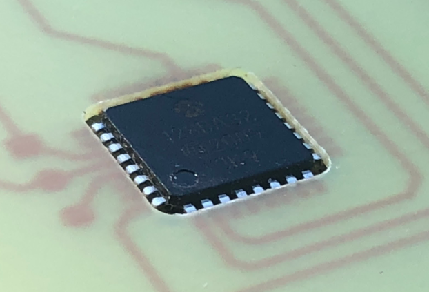
Card is a composition of two components. First component AVR128DA32 in TQFP package, device designations AVR128DA32-I/PT or AVR128DA32-E/PT.
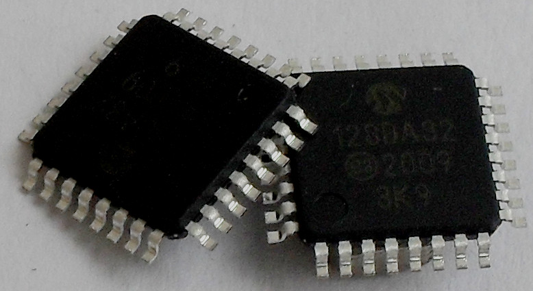
Microcontroller is available with a number of vendors.
For example:
https://www.tme.eu/en/details/avr128da32-i_pt/8-bit-avr-family/microchip-technology/ https://uk.farnell.com/microchip/avr128da32-e-pt/mcu-8bit-avr-24mhz-tqfp-32/dp/3481939?st=AVR128DA32 https://www.digikey.com/product-detail/en/microchip-technology/AVR128DA32-I-PT/150-AVR128DA32-I-PT-ND/12081922
Price of this component is below 2E.
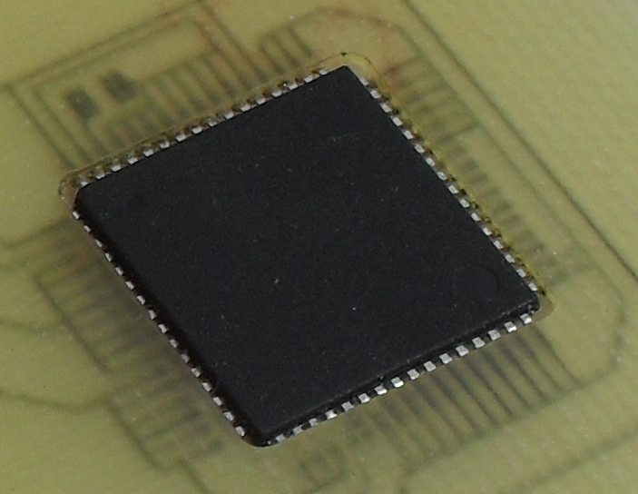
In years 2015-2019 the OsEID project, used the Atmega128 microcontroller. This component is still supported by OsEID project, but because price of this component is bigger and cryptographics operation took longer, AVR128DA is preferred microcontroller for future releases of OsEID project.
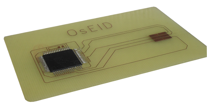
The second component is single sided printed circuit board (PCB) in the form of plastic payment card.
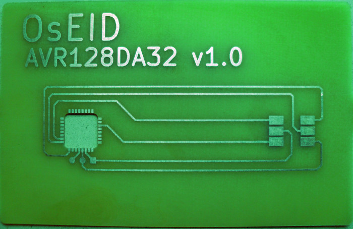
This board is designed to match card dimensions - as defined in ISO/IEC 7810, format ID-1 and card contact pads positions defined by ISO 7816-2. PCB also connects microcontroller leads to card contact pads.
There is no vendor for this PCB, but you can produce this PCB at your local PCB producer. Your producer needs Gerber file or PDF file or simple image as a manufacturing data for PCB production. Please check download section for these files. Thickness of PCB must be about 0.8mm to meet dimensions of card recommended by ISO/IEC 7810. Picture of PCB is also included in appendix A.
Soldering microcontroller to PCB
PCB and microcontroller together form final smartcard. The components are connected by soldering.
If we solder TQFP package directly on PCB board, we can achieve thickness slightly below 2mm. That is not good. To get minimal thickness of card, microcontroller is imbedded into printed circuit board. In the position of microcontroller there is a rectangular hole created in PCB (dimensions for AVR128DA32 about 8.3 x 8.3mm or 15.3 x 15.3 mm for ATmega128). The body of microcontroller is then inserted into this hole. Then microcontroller leads are slightly bent upwards and soldered to PCB copper contacts from opposite side as normally. This mounting can achieve final thickness of card about 1.1mm. Most of card readers deal with this thickness without problems.
|
|
Be aware that final thickness about 1.1mm violates ISO/IEC 7810 specification, which defines thickness of card to 0.76mm with tolerance +0.08mm. |
PCB dimensions must also match ISO/IEC 7810 specification: width 85.47mm - 85.72mm and height 53.92mm - 54.03mm, and corner radiuses in range 2.88 to 3.48mm.
It is assumed that you have plenty of mechanical skills and experience with soldering surface mounted integrated circuit. Further details of the mechanical installation are therefore not listed here.
PCB plating / coating
For amateur use, a common printed circuit board without special surface finish will be sufficient. Because copper on PCB corrodes on air, sooner or later, problems arise when using the card. If you plan to use the card frequently, it is advisable to use circuit board with gold-plated contact pads. An alternative to gold plating is silver plating or nickel plating. Consult your local printed circuit board producer what plating he offers and at what price.
Programming microcontroller
Before using the card, microcontroller must be programmed with card operation system. You need hex file card.hex that is available in download section. To load hex file into AVR128DA32 microcontroller, you need programmer tool with programmer software. AVR128DA uses UPDI interface, description of UPDI can be found in AVR128DA documentation but lot information can be found on internet, for example https://microchipdeveloper.com/atmelice:updi
Another open source software inclusive hardware description can be found at https://github.com/mraardvark/pyupdi or https://github.com/popovec/upditool
If you decide to use ATmega128 microcontroller, you can found information about programming at http://www.nongnu.org/avrdude/. Programmer hardware overview can be found at http://www.ladyada.net/learn/avr/programmers.html. You can learn more about programming AVR microcontrollers on internet, a good website to start is https://learn.adafruit.com/introducing-trinket/programming-with-avrdude.
At this point the familiarity with programming AVR microcontrollers through UPDI/ISP is assumed.
Your card already includes UPDI/ISP connector but in different format as normal Microchip/Atmel ISP6 or ISP10 connectors. Mapping microcontroller pins to card contact pads and to standard Microchip ISP6 can be found in the tables below.
| CPU pin name | ISO pad name | MICROCHIP name |
|---|---|---|
GND |
GND C5 |
GND 6 |
VDD |
VCC C1 |
VCC 2 |
PA3 |
RST C2 |
|
UPDI |
NC C6 |
UPDI_DATA 1 |
PA2 |
CLK C3 |
|
PA4 |
I/O C7 |
|
|
there is another UPDI connector at PCB, near microcontroller three pads UPDI/VDD/GND can be found. |
| CPU pin name | ISO pad name | Atmel ISP name |
|---|---|---|
GND |
GND C5 |
GND 6 |
Vcc |
VCC C1 |
VCC 2 |
RESET |
NC C6 |
RESET 5 |
PE0/PDI 2 |
RST C2 |
MOSI 4 |
PE1/PDO |
CLK C3 |
MISO 1 |
PB1/SCK |
I/O C7 |
SCK 3 |
|
|
PE1 pin is also connected to pin T3 on atmega128, this pin is not used in ISP programming mode, but used by card software as clock input from card reader. |
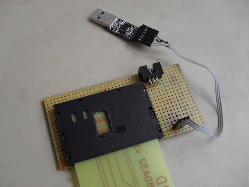
It is recommended to make simple adapter from AVR ISP6 connector to CARD contact pads. You need a smart card connector and a ribbon cable with IDC connector with 6 pins. Alternatively, if your programmer already contains ribbon cable with 6 pin female IDC connector, you need 6 pin male IDC connector. Make sure to create adapter with correct pinout as described in tables above.
Of course, you can use two 6 pins IDC connectors - one for ATmega ISP and one for AVR128DA UPDI programmer. You can use TTL to USB convertor as UPDI programmer, then 3 pins connector is enough.
You can buy it from here:
http://www.tme.eu/en/details/116b-dboa-r/card-connectors/attend/116b-dbo0-r02/
http://www.tme.eu/en/details/fc06150-s/ribbon-cables-with-idc-connectors/amphenol/
http://www.tme.eu/en/details/09185066324/idc-connectors/harting/
Carefully connect the cable to the relevant contact pads of smart card connector. Connect this adapter to AVR programmer, insert new card into smart card connector and you can upload firmware into your card.
Programming AVR128DA microcontroller:
fuse 1/BODCFG: 0x00
fuse 2/OSCCFG: 0x00
fuse 5/SYSCFG0: 0xC0
fuse 6/SYSCFG1: 0x00
fuse 7/CODESIZE: 0x80
fuse 8/BOOTSIZE: 0x80
Then upload card.hex file into microcontroller FLASH.
Lock the device by programming LOCK to value 0
Example for upditool:
$ upditool -P /dev/ttyUSB0 -p avr128da32 -U fuse5:w:0xc0:m -U fuse2:w:0:m
$ upditool -P /dev/ttyUSB0 -p avr128da32 -U fuse7:w:0x80:m -U fuse8:w:0x80:m
$ upditool -P /dev/ttyUSB0 -p avr128da32 -e -U flash:w:card.hex:i
$ upditool -P /dev/ttyUSB0 -p avr128da32 -U lock0:w:0:m
Example for pyupdi
$ pyupdi.py -c /dev/ttyUSB0 -d avr128da32 -fs 5:0xc0
$ pyupdi.py -c /dev/ttyUSB0 -d avr128da32 -fs 2:0x00
$ pyupdi.py -c /dev/ttyUSB0 -d avr128da32 -fs 7:0x80
$ pyupdi.py -c /dev/ttyUSB0 -d avr128da32 -fs 8:0x80
$ pyupdi.py -c /dev/ttyUSB0 -d avr128da32 -f card.hex
|
|
Warning, device remains in unlocked state. There is no support to program LOCK by this software (August 2020). |
Programming ATmega128 microcontroller:
It is recommended to program microcontroller fuses first:
Extended fuses: 0xFF
High fuses: 0xD9
Low fuses: 0x04
Then upload card.hex and at last step is programming lock bits:
Lock bits: 0xFC
Example for avrdude and avrispmkII programmer:
$ avrdude -p m128 -c avrispmkII -v -U efuse:w:0xFF:m
$ avrdude -p m128 -c avrispmkII -v -U hfuse:w:0xD9:m
$ avrdude -p m128 -c avrispmkII -v -U lfuse:w:0x04:m
$ avrdude -p m128 -c avrispmkII -v -U flash:w:download/OsEID_card.hex
$ avrdude -p m128 -c avrispmkII -v -U eeprom:w:download/OsEID_card_eeprom.hex
$ avrdude -p m128 -c avrispmkII -v -U lock:w:0xFC:m
Your card is ready for use now.
Compiling from sources
You can use source files to build card.hex. Development is tested on DEBIAN 10. You need gcc-avr, binutils-avr, avr-libc, make, srecord and avrdude package. For programming AVR128DA32 device, pyupdi or upditool is needed to (from github). You need to unpack OsEID tarball. Makefiles located in src subdirectory are used to compile and program the card. Card serial number is derived from AVR128DA serial number or for ATmega128 serial number is is automatically generated from actual time/date.
for AVR128DA based card (upditool programmer):
make -f Makefile.AVR128DA
make -f Makefile.AVR128DA program
make -f Makefile.AVR128DA lock
|
|
pyupdi programmer can be used to, (make -f Makefile.AVR128DA pyprog) but device remains in unlocked state. There is no support to program LOCK by this software (August 2020). |
for Atmega128 based card:
make -f Makefile.atmega128
make -f Makefile.atmega128 fuses
make -f Makefile.atmega128 program
make -f Makefile.atmega128 lock
|
|
avrispmkII programmer is expected |
Vpp pad
In year 2006, the standard ISO 7816 changed the definition of Vpp pad. This pad is no longer used for programming voltage. If you use newer reader (produced after 2006), card may work, or fail in this reader. If your OsEID card does not working in your card reader, Vpp pad on card must be isolated from reader. This can be done by stick self-adhesive tape on Vpp pad.
Known issue: Alcor Micro AU9560 USB reader - OsEID card (AVR128DA or Atmega128 based) is not working in this reader without Vpp pad isolation.
Building OsEID-token
Only partial information here, schematics, PCB and list of components is in Appendix D. It is assumed that only a skilled technician will try to build this device.
Using OsEID card
For linux users: download and install OpenSC package. Please use OpenSC version 0.19 or newer. Debian (buster) already contains the OpenSC version 0.19. For other distros, please follow distro specific installation of OpenSC package. Download and install pcscd and pcsc-tools package. According to your card reader, you will need to install specific driver for your reader (for example libccid or libacr38u package, .. )
Windows users: download and install OpenSC 0.17. (version 0.18 - 0.21 is only partially tested, please read comments about minidriver configuration below)
Base functionality
The fastest way to test the functionality of the card is by launching program pcsc_scan :
$ pcsc_scan
PC/SC device scanner
V 1.4.23 (c) 2001-2011, Ludovic Rousseau <ludovic.rousseau@free.fr>
Compiled with PC/SC lite version: 1.8.11
Using reader plug'n play mechanism
Scanning present readers...
0: Alcor Micro AU9540 00 00

Thu Dec 29 09:22:26 2016
Reader 0: Alcor Micro AU9540 00 00
  Card state: Card removed,
Insert card into reader. If the card is recognized, similar message is displayed:
Wed Jan  4 14:21:01 2017
Reader 0: Alcor Micro AU9540 00 00
  Card state: Card inserted,
  ATR: 3B F5 18 00 02 10 80 4F 73 45 49 44

ATR: 3B F5 18 00 02 10 80 4F 73 45 49 44
+ TS = 3B --> Direct Convention
+ T0 = F5, Y(1): 1111, K: 5 (historical bytes)
  TA(1) = 18 --> Fi=372, Di=12, 31 cycles/ETU
    129032 bits/s at 4 MHz, fMax for Fi = 5 MHz => 161290 bits/s
  TB(1) = 00 --> VPP is not electrically connected
  TC(1) = 02 --> Extra guard time: 2
  TD(1) = 10 --> Y(i+1) = 0001, Protocol T = 0
-----
  TA(2) = 80 --> Protocol to be used in spec mode: T=0 - Unable to change -
defined by interface bytes
+ Historical bytes: 4F 73 45 49 44
  Category indicator byte: 4F (proprietary format)
Press CTRL-C break pcsc_scan and you can go to configure OpenSC package.
OpenSC package configuration
If your OpenSC version is 0.20.0 or above, OsEID card is automatically recognized. For older versions you need do some changes in configuration.
Configure OpenSC package: edit /etc/opensc/opensc.conf
or if you use windows C:\Program Files\OpenSC Project\OpenSC\opensc.conf
add new [ATR] for OsEID card and OsEID token in app default section:
        # OsEID card is handled by myeid driver
        card_atr 3b:f5:00:00:02:10:80:4f:73:45:49:44 {
                atrmask = "ff:ff:00:ff:ff:ff:ff:ff:ff:ff:ff:ff";
                driver = "myeid";
        }
        # OsEID token, T0/T1 protocol
        card_atr 3b:f5:00:00:02:80:01:4f:73:45:49:44:00 {
                atrmask = "ff:ff:00:ff:ff:ff:ff:ff:ff:ff:ff:ff:00"
                driver = "myeid";
        }
If your OpenSC version is 0.20 or newer, and your using OsEID card with firmware 20190102 or older, you need one more configuration directive in /etc/opensc/opensc.conf in app default section:
        reader_driver pcsc {
                max_recv_size = 255;
        }
It is recommended that you install oseid profile files into OpenSC profile directory (usually /usr/share/opensc/). Profile files for different versions of OpenSC can be found in download directory.
After this configuration step, you can use opensc-explorer, pkcs15-init, pkcs15-tool, pkcs11-tool and other software to personalize your OsEID card.
Windows minidriver configuration
If you plan to use OsEID card in Win 10 (for example in EDGE browser etc.) you need install OpenSC package
OpenSC version 0.22.0-rc1 functionality with OsEID card has been tested in WIN 10, certutil command is fully functional and TLS client auth in EDGE browser is working.
To use OsEID card, with minidriver, you need to update your registry file. Please use OsEID.reg file from download section. Here example used for opensc 0.22.0-rc1:
[HKEY_LOCAL_MACHINE\SOFTWARE\Microsoft\Cryptography\Calais\SmartCards\OsEID-old]
"80000001"="C:\\Program Files\\OpenSC Project\\OpenSC\\minidriver\\opensc-minidriver.dll"
"ATR"=hex:3b,f5,00,00,02,10,80,4f,73,45,49,44
"ATRmask"=hex:ff,ff,00,ff,ff,ff,ff,ff,ff,ff,ff,ff
"Smart Card Key Storage Provider"="Microsoft Smart Card Key Storage Provider"
"Crypto Provider"="OpenSC CSP"

[HKEY_LOCAL_MACHINE\SOFTWARE\Microsoft\Cryptography\Calais\SmartCards\OsEID]
"80000001"="C:\\Program Files\\OpenSC Project\\OpenSC\\minidriver\\opensc-minidriver.dll"
"ATR"=hex:3b,d5,96,02,80,31,fe,65,4f,73,45,49,44,1f
"ATRmask"=hex:ff,ff,ff,ff,ff,ff,ff,ff,ff,ff,ff,ff,ff,ff
"Smart Card Key Storage Provider"="Microsoft Smart Card Key Storage Provider"
"Crypto Provider"="OpenSC CSP"

[HKEY_LOCAL_MACHINE\SOFTWARE\Microsoft\Cryptography\Calais\SmartCards\OsEID-token]
"80000001"="C:\\Program Files\\OpenSC Project\\OpenSC\\minidriver\\opensc-minidriver.dll"
"ATR"=hex:3b,f5,00,00,02,80,01,4f,73,45,49,44,00
"ATRmask"=hex:ff,ff,00,ff,ff,ff,ff,ff,ff,ff,ff,ff,00
"Smart Card Key Storage Provider"="Microsoft Smart Card Key Storage Provider"
"Crypto Provider"="OpenSC CSP"
For 32 bit OpenSC version on 64 bit system there is small change in minidriver path:
"80000001"="C:\Program Files (x86)\OpenSC Project\OpenSC\minidriver\opensc-minidriver.dll"
After personalizing your card, you need to use certutil -scinfo command in windows command prompt to import certificates from card into windows certificate store. After successful import of certificates, you can browse personal certificates by certmgr and/or certlm command.
Explore files on card:
On linux/windows with installed OpenSC package You can use opensc-explorer to browse files on Your new card:
$ opensc-explorer
OpenSC Explorer version 0.14.0
Using reader with a card: ACS ACR38U 00 00
OpenSC [3F00]> info

Dedicated File  ID 3F00

File path:     3F00
File size:     32767 bytes
ACL for SELECT:       N/A
ACL for LOCK:         N/A
ACL for DELETE:       CHV3
ACL for CREATE:       CHV3
ACL for REHABILITATE: N/A
ACL for INVALIDATE:   N/A
ACL for LIST FILES:   N/A
ACL for CRYPTO:       N/A
ACL for DELETE SELF:  N/A
Proprietary attributes:  00 02
Security attributes:     33 3F FF
There exists only one file on card. This is file with ID 3F00 - master file (MF). Card security system (PIN/PUK codes) are inactive for now.
Card initialization (creation of pkcs15 structure)
pkcs15-init -C --so-pin 00000000 --so-puk 00000000 --pin 1111111
or better way, determine OpenSC version by running
opensc-tool -i
Then use oseid profile with the same version as OpenSC (for example 0.20):
pkcs15-init -C -c oseid_0.20 --so-pin 00000000 --so-puk 00000000 --pin 1111111
Init user pin/puk
pkcs15-init --store-pin --id 01 --pin 11111111 --puk 11111111 --so-pin 00000000
Finalize card (activate card security mechanism)
pkcs15-init -F
Generate RSA key
(Warning, this operation is really slow, may run about 3 minutes but in some cases over 30 minutes for 1024 bit key, generating 2048 bit key take about 45 minutes but in some cases several hours.)
pkcs15-init --generate-key rsa/1024 --auth-id 1 --pin 11111111 \
  --label gen_rsa_1024 --key-usage sign,decrypt
Generate RSA key with openssl and upload RSA key
openssl genrsa -out 1024-key.pem 1024
pkcs15-init  --store-private-key 1024-key.pem --auth-id=1 --pin 11111111 \
  --key-usage sign,decrypt --id 1234
Sign message with RSA key
pkcs11-tool  --sign --slot 0 -m SHA1-RSA-PKCS --id 1234 -pin 11111111 \
  --input-file rsa_sign_testfile.txt --output-file rsa_sign_testfile.txt.sign
Generate EC key on card
|
|
For EC operations you need an OpenSC version 0.17 or newer version. |
pkcs15-init --generate-key ec-prime256v1 --auth-id 1 --pin 11111111
Generate key with openssl and upload EC key/certificate to card
openssl ecparam -name prime256v1 -genkey -noout -out prime256v1-key.pem
pkcs15-init --store-private-key prime256v1-key.pem  --auth-id=1 --pin 11111111

pkcs15-init -X prime256v1-cert.pem --pin 11111111 --auth-id=1
Sign with EC key
First read possible keys, select proper key id for sign (in example 121212)
pkcs15-tool --list-public-keys
pkcs15-crypt --pin 11111111 -k 121212 --signature-format "openssl" -s \
  -i testfile.txt.sha1 -o testfile.txt.pkcs11.sha1.sig
Another example for sign with EC key:
pkcs11-tool --sign --signature-format "openssl" --slot 1 -m ECDSA \
  --input-file sign.this.txt --output-file sign.this.txt.signature
OsEID-tool
You can use OsEID-tool software (available in tools section, only linux version). This software is designed to simplify some tasks on OsEID card (can be used with MyEID card too). Implemented functions:
INFO - print info about card
INIT - do initialization of token by pkcs15-init
EC-CREATE-KEYS - use openssl to generate EC keys
EC-UPLOAD-KEYS - upload EC keys into initialized token
EC-GENERATE-KEYS  - generate keys on card
EC-SIGN-TEST - sign sample text by ECDSA operation and test this signature
EC-ECDH-TEST - generate shared secrets and test shared secrets
RSA-CREATE-KEYS -  use openssl to generate RSA keys
RSA-UPLOAD-KEYS - upload RSA keys into initialized token
RSA-GENERATE-KEYS - generate RSA key on card
RSA-SIGN-TEST - sign sample text with token RSA operation and test this signature
RSA-DECRYPT-TEST - decrypt test data
PKCS11-RSA-TEST - pkcs11-tool full test on RSA keys
CSR [key] [subject] - generate certificate signing request
CRT [key] [subject] - generate self signed certificate
RND-TEST - test random generator entropy
FAQ
What is OsEID ?
OsEID is smart card with cryptography support, realized in amateur conditions. It consist of one integrated circuit (microcontroller Microchip/Atmel ATmega 128) and PCB (printed circuit board). No more components are needed.
What can OsEID handle ?
OsEID smart card supports both RSA cryptography and Elliptic curve cryptography. DES and AES ciphers are supported too. It is (partially *) compatible with ISO 7816 specifications. Card support PKCS15 structure, RSA up to 2048 bits and NIST elliptic curves (192,256,384 and 521 bits).
It is designed to emulate Aventra MyEID card in universal microcontroller. No special driver is needed for use in Linux/Windows.
What difference is between MyEID and OsEID card?
OsEID is hobby/amateur smart card, MyEID is professional card. OsEID come with open source firmware in well known, easily accessible and inexpensive microcontroller.
Where do I buy a card ?
The card can not be bought, You have to make it. (Read documentation chapter Making OsEID card)
Where can I find the latest firmware version ?
New versions are published on https://sourceforge.net/projects/oseid This is a primary site, code is available in tarball (all sources, firmware files compiled from sources in HEX format, and PDF version of doc).
Same site can be reached at https://oseid.sourceforge.io
OsEID is also available on github - https://github.com/popovec/oseid
OsEID development track all changes in OpenSC MyEID driver. All changes in OpenSC thats affect correct functions of OsEID card are examined and a update is uploaded into https://github.com/popovec/oseid. You usually need these updates only if you use development versions of OpenSC.
HTTP online doc is available on https://popovec.github.io/OsEID
In what application I can use this smart card ?
-
openssh - private rsa key can be stored on card
-
Firefox - secure login into web pages
-
windows Edge - secure login into web pages (tested with opensc 0.17)
-
Thunderbird - sign and decrypt emails
-
openvpn - secure login to openvpn server
-
easy-rsa - sign certificates by private key on card
-
linux server/desktop - two-factor authentication
Why RSA calculation is so slow?
AVR128DA32 is 8 bit CPU and runs at low frequency (about 27MHz). The chip has only 8x8 bit multiplier, no special acceleration units for RSA and ECC, as it is in the world of commercial cards.
I found a bug in OsEID card, where can I report it ?
You can contact me (author) by email <popovec.peter@gmail.com>
Card communication protocol
Application uses formatted data blocks to communicate with card. This data blocks are APDUs - Application Protocol Data Units.
APDU is constructed as block of bytes. There exists two types of APDU, command and response.
Command APDU consist of four bytes and optional fields Lc, DATA and Le
CLA |
INS |
P1 |
P2 |
Lc |
DATA |
Le |
Response APDU consist of optional response body and two status bytes:
RDATA |
SW1 |
SW2 |
There exist four formats of command APDU:
-
No command body, no response body
-
No command body, response
-
Command body, no response
-
Command body, response body
Short APDU allow maximal length of DATA field 255 bytes, extended APDU allow maximal length of DATA field up to 65535 bytes.
ISO7816-3 defines numbers Nc and Ne that corresponds to fields Lc and Le. If Nc is 0, Lc field is not present, Nc in range 1..65535 corresponds to Lc in same range. Similar mapping from Ne to Le exist, but Ne is in range 0..65536.
Nc value represent length of DATA field, Ne represent maximal length of response body (below). Lc/Le is coded in zero, one, two or three bytes, coding depends on APDU case:
CASE 1: Nc = 0, Ne = 0, Lc,DATA,Le not present in APDU, APDU length = 4
CASE 2: Nc = 0, Ne > 0, Le present in APDU, APDU length = 5 or 7
-
(S) one byte in range 1..255 → Le in range 1.255
-
(S) one byte 0 → Le = 256
-
(E) one byte 0 and two bytes (big endian) Le 1..65536 (value 0 represent 65536 bytes for Le)
CASE 3: Nc > 0, Ne = 0, Lc, and DATA present in APDU
-
(S) one byte in range 1..255 → Lc in range 1.255, APDU length 5+Lc
-
(E) one byte 0 and two bytes (big endian) Lc 1..65535, APDU length 7+Lc
CASE 4: Nc > 0, Ne > 0, Lc,DATA,Le present in APDU
-
(S) one byte in range 1..255 as Lc, DATA (Lc bytes), one byte Le in range 0..255, represent maximum response length (0=256 bytes). APDU length = 6+Lc
-
(E) one byte 0, two bytes Lc, DATA (Lc bytes max 65535, 0 is not allowed value here), two bytes, Le (value 0 represent 65536 bytes of response) APDU length = 9+Lc
Here (S)/(E) is used to mark Short or Extended variant of APDU.
Application access card over card reader, card reader uses communication protocol to transport APDU from application to card and from card. This low level transport uses Transport Protocol Data Unit - TPDU.
APDU is mapped into TPDU, but mapping depends on card communication protocols. OsEID card uses T0 protocol. T0 protocol is byte oriented protocol. OsEID token can use T0 or T1 protocol.
APDU mapping to T0 protocol
Card is always waiting for 5 bytes (header):
CLA |
INS |
P1 |
P2 |
P3 |
CLA, INS, P1,P2 and P3 bytes are transmitted to card. P3 byte is used to inform card about optional command body or requested size of returned data. What exactly P3 represent (command body or response length) is determined from INS byte.
Header is transmitted, then reader is waiting for procedure byte from card. If this procedure byte is not received until some time, card reader reject card as unresponsive.
How procedure byte is processing is described in ISO7816-3/10.3.3 table 11. If procedure byte is 0x60 (NULL), card reader only extend working time and is waiting for new procedure byte. This is used by card to inform card reader that more time is needed for processing message. This prevent rejecting card as unresponsive.
If 0x6X or 0x9X is received as procedure byte, this is handled as SW1 (status word), then whole status word (and next byte SW2) is returned to application.
If card reader receives INS (or INS negated, but this in not used in OsEID), card reader send rest of APDU to card (or receives data from card). Another values in procedure byte are not allowed.
From ISO7816-3/10.3.1: It is assumed that the card and the interface device know a priori the direction of transfer… How this can be fulfilled ?
From reader view (only short cases of APDU):
CASE 1 (APDU length 4 bytes) - no Lc, no Le. (Nc = 0, Ne = 0). Because header length is 5 bytes, P3 byte is set to 00. Header is sent to card. Card does not expect data field of APDU because P3 must be interpreted as Le field (Lc field is not allowed to be zero). T0 protocol does not allow us to inform card about Ne = 0 - P3 is interpreted as Le field and card accept this as Ne = 256.
Expected response is 2 bytes SW1,SW2. After receiving procedure byte, reader test this byte (NULL,INS,SW), and if this is not SW, new procedure byte is waiting.
CASE 2 (APDU length 5 bytes), header is sent to card, P3 represent the Le, Lc is not present. Expected response length is P3 + 2 (SW1,SW2) bytes, for P3=0, 256 +2 bytes. After receiving procedure byte, reader test this byte, and if this is INS, reader reads expected response bytes. Of course, card may return different size of response as expected, this is not an error.
CASE 3 (APDU length 5 + P3 bytes), header is sent to card, P3 represent the Lc, Le is not present. Expected response is 2 bytes (SW1,SW2). After receiving procedure byte, reader test this byte, and if this is INS, reader transmit P3 bytes (DATA field of APDU) to card, then new procedure byte is waiting.
CASE 4 (APDU length 5 + P3 + 1 bytes) - same as for CASE 3 (there is no way to transport Le to card).
Card assumes that Ne = 256 in this case. Card prepares response data and signalize back to reader how many data bytes can be returned in next command ( by SW1 = 0x61 or SW1=0x6C, SW2 is length of data, if SW2 is 0, 256 or more data bytes are available). It is expected, that card reader/application software then uses GET RESPONSE command for receiving the data, and Ne is handled in procedure that generated GET RESPONSE command.
From card view:
Card is waiting for 5 bytes from reader. These bytes represent the header of APDU. If P3 is 0, this can not be a Lc field, P3 is then accepted as Le. If Lc is not present in APDU, then DATA field is absent too. This correspond to CASE 1 or CASE 2 APDU with Ne= 256.
If P3 != 0, this is CASE 2 or CASE 3 or CASE 4. We need INS to determine APDU CASE 2 - only this case need transfer from card to reader. For CASEs 3,4 Ne is assumed to be 256, P3 is Lc/Nc. For CASE 2 Nc is 0, P3 is Le/Ne.
Exact definition if INS represent CASE 2 APDU is not available in ISO7816.
From ISO7816-4 all commands where Nc=0 can be assumed as candidate for APDU CASE 2.
INS |
command name |
OsEID |
allowed cases |
card to ICC |
04 |
DEACTIVATE FILE |
|||
0C |
ERASE RECORD |
CASE 1 |
||
0E |
ERASE BINARY |
* |
CASE 1,3 |
|
0F |
ERASE BINARY |
CASE 1,3 |
||
10 |
PERFORM SCQL OPERATION |
|||
12 |
PERFORM TRANSACTION OPERATION |
|||
14 |
PERFORM USER OPERATION |
|||
20 |
VERIFY |
* |
CASE 1,3 |
|
21 |
VERIFY |
CASE (1?),3 |
||
22 |
MANAGE SECURITY ENVIRONMENT |
* |
CASE 1,3 |
|
24 |
CHANGE REFERENCE DATA |
* |
CASE 3 |
|
26 |
DISABLE VERIFICATION REQUIREMENT |
CASE 1,3 |
||
28 |
ENABLE VERIFICATION REQUIREMENT |
CASE 1,3 |
||
2A |
PERFORM SECURITY OPERATION |
* |
CASE 3,4 |
|
2C |
RESET RETRY COUNTER |
* |
CASE 1,3 |
|
44 |
ACTIVATE FILE |
* |
CASE (1,3?) |
|
46 |
GENERATE ASYMMETRIC KEY PAIR |
* |
CASE 1,3,4 |
|
70 |
MANAGE CHANNEL |
CASE 1,2 |
||
82 |
EXTERNAL AUTHENTICATE |
CASE 1,3 |
||
84 |
GET CHALLENGE |
* |
CASE 2 |
* |
86 |
GENERAL AUTHENTICATE |
* |
CASE 3,4 |
|
87 |
GENERAL AUTHENTICATE |
CASE 3,4 |
||
88 |
INTERNAL AUTHENTICATE |
CASE 4 |
||
A0 |
SEARCH BINARY |
CASE (1,2,3,4?) |
||
A1 |
SEARCH BINARY |
CASE 3,4 |
||
A2 |
SEARCH RECORD |
CASE 3,4 |
||
A4 |
SELECT |
* |
CASE 1,2,3,4 |
|
B0 |
READ BINARY |
* |
CASE 2 |
* |
B1 |
READ BINARY |
CASE 2,4 |
||
B2 |
READ RECORD |
CASE 2 |
||
B3 |
READ RECORD |
CASE 2,4 |
||
C0 |
GET RESPONSE |
* |
CASE 2 |
* |
C2 |
ENVELOPE |
CASE (1,3,4?) |
||
C3 |
ENVELOPE |
CASE (1,3,4?) |
||
CA |
GET DATA |
* |
CASE 2,(4?) |
* |
CB |
GET DATA |
CASE 2,4 |
||
D0 |
WRITE BINARY |
CASE 3 |
||
D1 |
WRITE BINARY |
CASE 3 |
||
D2 |
WRITE RECORD |
CASE 3 |
||
D6 |
UPDATE BINARY |
* |
CASE 3 |
|
D7 |
UPDATE BINARY |
CASE 3 |
||
DA |
PUT DATA |
* |
CASE 3 |
|
DB |
PUT DATA |
CASE 3 |
||
DC |
UPDATE RECORD |
CASE 3 |
||
DD |
UPDATE RECORD |
CASE 3 |
||
E0 |
CREATE FILE |
* |
CASE 3 |
|
E2 |
APPEND RECORD |
CASE 3 |
||
E4 |
DELETE FILE |
* |
CASE 1,3 |
|
E6 |
TERMINATE DF |
CASE 1 |
||
E8 |
TERMINATE EF |
CASE 1 |
||
FE |
TERMINATE CARD USAGE |
CASE 1 |
OsEID column is checked for all INS supported by OsEID.
Some CASEs are marked by ?, if you need exact explanation about this INS/APDU CASE, you need to read whole ISO7816. ISO7816 is not precise enough, for example:
ENVELOPE ISO7816-4/7.6.2 Lc field present for encoding Nc > 0, there is no variant Nc=0, but .. ISO7816-3/12.2.7 describes use of ENVELOPE command and say: The absence of data bytes means "end of data string". In this case Nc=0.
Last column in the table represent INS that need transfer from card to reader. Conservative implementation in OsEID uses only GET RESPONSE command that need transfer from card to reader, because any other commands can generate status 0x61XX and then GET RESPONSE is used to return data.
Extended APDU in T0 protocol
Card does not have enough information about APDU case after header is received. Still INS and P3 can be used to allow transport of extended APDUs over T0 protocol.
There is no way to transport command APDU with data field > 255. Response APDU can transport at maximum 256 byte of response in one APDU. In some cases (Nc<256, Ne>256), extended APDU can be mapped to multiple APDUs to allow receive more than 256 bytes of response.
From card view:
If card receives P3 == 0, then card assumes CASE 1 or CASE2S/E - same action as for short APDUs. INS can be used to determine CASE 1 or CASE 2S/E. For CASE 2 card assumes Ne 256 or more bytes (for example, RSA 4096 sign operation a priori generates response with 512 bytes), and returns status 0x61XX. Application software then reads up to Ne bytes by GET RESPONSE command. Of course, card may return some data and status 0x9000 - this signalize us, that no more data are available, or new 0x61XX or 0x6cXX status signalize us more data are available - GET RESPONSE is then used until Ne bytes are received or status word 0x9000 is returned.
What about CASE 3E and 4E?, if Nc is < 256, P3 is set (in card reader or application software) to Nc and process continues in same way as for CASE 2 S/E. For Nc > 255 ENVELOPE command can be used (not allowed for now in OsEID). Alternative to ENVELOPE command is APDU chaining (described below).
Examples for T0 protocol
Transmit single command (select MF)
CLA |
INS |
P1 |
P2 |
P3/Lc |
DATA |
Le |
|
APDU |
00 |
A4 |
00 |
00 |
00 |
empty |
100 |
P3 in this case represent Lc field, value 0 determines here no command body. Card responds with two bytes SW1,SW2.
SW1 |
SW2 |
61 |
05 |
If SW1 is 0x61, and SW2 is zero, this signalize us, that 256 or more data can be received from card. If SW2 is in range 1..255, this represent exact number of bytes that can be received from card. To receive response, GET RESPONSE command is used:
CLA |
INS |
P1 |
P2 |
P3 |
00 |
C0 |
00 |
00 |
05 |
In this case, P3 represent Le field in APDU (requested Le 100 is reduced to number of bytes signalized by SW2 from card, ISO7816-3 describes value Na - bytes available), here 5 bytes is requested from card. Card return 5 bytes and new status word SW1,SW2:
RDATA |
SW1 |
SW2 |
00 01 02 00 01 |
90 |
00 |
If SW2 signalize us than 5 bytes are available in card, we can receive only part of data from card:
CLA |
INS |
P1 |
P2 |
P3 |
00 |
C0 |
00 |
00 |
03 |
Then response consist from RDATA of maximal length of 3 bytes and new status word SW1,SW2 signalize us, than two more bytes are available in card. (can be received by subsequent GET RESPONSE command)
RDATA |
SW1 |
SW2 |
00 01 02 |
61 |
02 |
If GET RESPONSE command set P3 byte to value greater that SW2 (in case SW1 ==0x61), then card return new status word:
SW1 |
SW2 |
6c |
02 |
this signalize us, that exact two bytes are available.
Application software repeat GET DATA command to receive all data from card, last status word 0x9000 terminates this loop. All data are concatenated into RDATA and last status word is appended to this block. This response is then returned as response APDU. If RDATA is longer that requested Le in command APDU, or some of status word SW1,SW2 signalize warning or error, only status word is returned as response APDU.
Transmit command with data field
CLA |
INS |
P1 |
P2 |
P3 |
DATA1 |
DATA2 |
00 |
A4 |
00 |
00 |
02 |
3f |
00 |
This transmit is splitted into two parts, card first receive 5 bytes. If P3 is not ZERO, INS is checked to determine meaning of P3 value. In case of SELECT command, card return INS byte back to reader (as procedure byte) and then card is waiting for P3 bytes from reader as DATA.
Response to this command is handled in same way as in previous example - GET RESPONSE is used to receive RDATA from card.
T0 protocol limitation allow us to send at maximum 255 bytes of DATA bytes.
ENVELOPE command should be used to transmit more data in T0 protocol (Please read ISO7816-3 12.2.7 for details), but this is not enabled in OsEID card for now (due limited flash size)..
Alternative method may use APDU chaining (ISO7816-4 5.1.1.1).
If command generates response 256 or more bytes, 1st status word is 0x6100, and GET RESPONSE is then used to read 256 bytes of response. New status word (from GET RESPONSE command) then can signalize end of transport (0x9000) or sets SW1 to 0x61 and SW2 to remaining bytes count.
Read data from card (no data block in command)
CLA |
INS |
P1 |
P2 |
P3 |
00 |
B0 |
00 |
00 |
9 |
If INS defines read operation (in example READ BINARY operation), P3 value is used as number of returned bytes for subsequent GET RESPONSE command. If P3 is ZERO, this mean 256 bytes is to be returned by card.
After card receive this command, there is no INS byte returned back to reader (as in previous example), but SW1,SW2 is returned. If SW1 is 0x61, similar procedure as in previous example can be used to read response.
An attentive reader may notice, that card reader must support (for T0 protocol) transport of 5+255 bytes to card and 256+2 bytes from card in one transport.
APDU mapping to T1 protocol
T1 protocol uses packet oriented transport to and from card. For details about this, please read ISO7816-3/11. APDU is splitted into I frames and then reassembled in card back to original APDU. State machine for this can be found in opensource project [CCIDusb], in directory src/towitoko/ and src/openct/proto-t1.c. Reverse joining of I frames can be found in OsEID sources, in file targets/xmega128a4u/ccid.c. Of course, response APDU is splitted in card and reassembled in reader/host.
If command APDU uses short case 4 (described above), reader must support at minimal transport for 4+1+255+1 = 261 bytes.
If command APDU uses extended case 4, then minimal transport size is 4+3+256+2 = 265 bytes, and for maximal Lc 4+3+65535+2 = 65544 bytes.
Transport of responses must support 65536+2 bytes.
OsEID token integrated CCID reader allow transport of 271 bytes in one transport (dwMaxCCIDMsgLen = 271). CCID header need 10 bytes overhead, then maximal message length is 261 bytes. Because I frames are chained, there is no limitation in transport of extended APDU over T1 protocol, T0 is limited - max 255 bytes in DATA field.
In this documentation APDU - TPDU mapping is described for all commands (T0 protocol). Bytes CLA, INS, P1, P2 from APDU is mapped to TPDU without change, byte P3 in TPDU is mapped to Lc or Le field of APDU.
APDU chaining
APDUs CASE 3S/E and 4S/E can be chained. CLA must be set 0x10 for any chained APDU and last APDU in chain must have CLA = 0. For any APDU in chain with CLA 0x10 Le field is ignored. Only Le field from last APDU in chain (CLA=0) is used. OsEID allows to chain CLASS 3S with CASE 3E or 4S/4E APDUs. Detail about APDU chaining can be found in ISO7816-4/5.1.1.1
Warning, OsEID for now does not have support for signalizing card capabilities (ISO7816-4/8.1.1.2.7) and because this, APDU chaining is not signalized.
Filesystem
Card uses a simple filesystem compatible with ISO7816. However, the functions of filesystem do not meet all the requirements defined in ISO7816. Please, follow the comments on these inconsistencies in the following text.
Filesystem is in ATMEGA FLASH. Security data (PINs, PUKs) are stored in ATMEGA EEPROM. Filesystem is organized as simple linear structure, header, file, header, file…. header, file. Simplicity of filesystem limits file delete operation. Delete operation only marks file as deleted. Deallocation of file space is available only for files at end of filesystem. There does not exist any CRC data checks or other consistency check in filesystem. (Already a BETA version of FLASH friendly COW filesystem exists, with CRC and other features, but not open source for now. Because of the code size it may not be available at all. The development is currently frozen.)
File size is limited to max 32767 bytes, DF files are always auto sized. If DF file is created, only the space for file header is allocated in card. DF file does not contain information about children, but children know what DF is their parent. There is no limit on number of files on card. Filesystem limit is 65536 bytes. (MyEID uses PUT DATA: INITIALIZE APPLET to set maximum number of files, this operation is supported, but value is ignored.)
Filesystem on blank card already contain two files, the file with ID=3F00 (MF) at top level and DF with ID 5015. There is way to remove the DF 5015, please read PUT DATA: INITIALIZE APPLET command description. There is difference in MyEID and OsEID card, new MyEID card comes with different security attributes.
MyEID (ver 3.3.3/4.0.1                  OsEID:

OpenSC [3F00]> info                     OpenSC [3F00]> info

Dedicated File  ID 3F00                 Dedicated File  ID 3F00

File path:     3F00                     File path:     3F00
File size:     32767 bytes              File size:     32767 bytes
ACL for SELECT:       N/A               ACL for SELECT:       N/A
ACL for LOCK:         N/A               ACL for LOCK:         N/A
ACL for DELETE:       CHV3              ACL for DELETE:       CHV3
ACL for CREATE:       CHV3              ACL for CREATE:       CHV3
ACL for REHABILITATE: N/A               ACL for REHABILITATE: N/A
ACL for INVALIDATE:   N/A               ACL for INVALIDATE:   N/A
ACL for LIST FILES:   N/A               ACL for LIST FILES:   N/A
ACL for CRYPTO:       N/A               ACL for CRYPTO:       N/A
ACL for DELETE SELF:  N/A               ACL for DELETE SELF:  N/A
Proprietary attributes:  00 02          Proprietary attributes:  00 02
Security attributes:     33 3F FF       Security attributes:     11 3F FF

OpenSC [3F00]> cd 5015                  OpenSC [3F00]> cd 5015
OpenSC [3F00/5015]> info                OpenSC [3F00/5015]> info

Dedicated File  ID 5015                 Dedicated File  ID 5015

File path:     3F00/5015                File path:     3F00/5015
File size:     32767 bytes              File size:     32767 bytes
DF name:     \xA0\x00\x00\x00cPKCS-15   DF name:     \xA0\x00\x00\x00cPKCS-15
ACL for SELECT:       N/A               ACL for SELECT:       N/A
ACL for LOCK:         N/A               ACL for LOCK:         N/A
ACL for DELETE:       NEVR              ACL for DELETE:       CHV1
ACL for CREATE:       CHV3              ACL for CREATE:       CHV1
ACL for REHABILITATE: N/A               ACL for REHABILITATE: N/A
ACL for INVALIDATE:   N/A               ACL for INVALIDATE:   N/A
ACL for LIST FILES:   N/A               ACL for LIST FILES:   N/A
ACL for CRYPTO:       N/A               ACL for CRYPTO:       N/A
ACL for DELETE SELF:  N/A               ACL for DELETE SELF:  N/A
Proprietary attributes:  00 02          Proprietary attributes:  00 02
Security attributes:     33 FF FF       Security attributes:     11 1F FF
If MyEID/OsEID card is erased by pkcs15-init -E command, security attributes are set at same values as described here for OsEID card.
|
|
hexadecimal values in next text are prefixed by 0x or suffixed by h for example 0x45 or 45h. In some cases, hexadecimal values are without prefix/suffix, but it can be deduced from context that this number is hexadecimal. Sorry about this. This doc is only a draft, not the final version. |
|
|
OsEID documentation is still incomplete, please consult MyEID reference manual 2.1.4, lot of MyEID APDUs are identical with OsEID APDUs. Do not expect a completely identical functions, keep in mind, OsEID is a hobby card. |
SELECT FILE
Selection mechanism manages current DF and current EF. If EF is selected, parent DF is set as current DF.
| CLA | INS | P1 | P2 | P3/Lc | DATA | Le |
|---|---|---|---|---|---|---|
0x00 |
0xA4 |
… |
… |
… |
… |
… |
(CASE 1S, CASE 2S, CASE 3S, CASE 4S)
-
P1 - see below
-
P2 - 0 = return [FCI] of selected file, 0x0c - return status only
TPDU: - P3 - in range 0..0xff, corresponding to DATA field length
APDU: - Lc corresponding to DATA field length - Data length corresponding to Lc - Le maximal size of response
|
|
If Le field is absent (T1 protocol) MyEID (4.0.1) still return FCI, OsEID return only status bytes. ISO7816-4:2005(E)/7.1.1: "If the Le field is absent, .. the response data field shall also be absent." |
Select file is controlled by P1, P2 parameters. There are several P1, P2 valid combinations. For some of combinations Lc != 0 and data field must contain specific data
-
P1 = 0, P2 == 0, P3 = 0, no Lc field T0 protocol: CASE 2 APDU, P3 must be set to 0 - corresponds to Ne=256 T1 protocol: CASE 1 APDU, there is no Lc/DATA/Le field T1 protocol: CASE 2 APDU, P3 correspond to Le field Select MF (0x3f00)
For rest of commands P2 is 0 or 0x0c:
-
P1 = 3, P3 = 0, no Lc field T0 protocol: CASE 2 APDU, P3 must be set to 0 - corresponds to Ne=256 T1 protocol: CASE 1 APDU, there is no Lc/DATA/Le field T1 protocol: CASE 2 APDU, P3 correspond to Le field Select parent DF of the current DF
-
P1 = 8, P3/Lc >=2, Lc even, Data represents IDs of path to file: Select by path from MF (CASE 3/4)
-
P1 = 9, P3/Lc >=2, Lc even, Data represents IDs of path to file: Select by path from current DF (CASE 3/4)
-
P1 = 4, P3/Lc >0, Lc < 17, Data represents filename: Select DF by name (CASE 3/4)
-
P1 = 1, P3/Lc = 2, Data file ID: Select child DF (CASE 3/4)
-
P1 = 2, P3/Lc = 2, Data file ID: Select EF under current DF (CASE 3/4)
-
P1 = 0, P2 = 0, P3/Lc = 2, Data = 0x3f00: Select MF (CASE 3/4)
-
P1 = 0, P3=Lc = 2, Data = ID: Firstly the file with ID in all children of selected DF is searched, if ID is found, FCI/status is returned. If previous search fails, test if parent of selected file matches ID. If this fails too, file in neighbors of selected file is searched. (CASE 3/4)
-
P2 = 0x0c - do not return [FCI]/[FCP]/[FMD]. This is usefull for T0 protocol, where Ne is assumed to be 256. Same functionality can be achieved if T1 protocol is used and Le is not present in APDU.
If select command failed, last correctly selected file remains selected.
MyEID difference: MyEID (according MyEID reference manual 2.1.4) does not support values 1,2,3 for P1. MyEID does not support P2 = 0x0c. MyEID uses T1 protocol, FCI is always returned even Le is not present in APDU (tested on MyEID 3.3.3/4.0.1).
CREATE FILE
| CLA | INS | P1 | P2 | P3/Lc | DATA | Le |
|---|---|---|---|---|---|---|
0x00 |
0xE0 |
0x00 |
0x00 |
… |
… |
empty |
(CASE 3S)
TPDU: - P3 - in range 18..255, corresponding to DATA field length
APDU: - Lc corresponding to DATA field length 18..255 - DATA length corresponding to Lc - Le empty
Data must contain File Control Parameters (FCP) information.
First byte (0x62) represents FCP tag, second byte represents sum of length of all tags in structure. The rest of structure is formed by TLV items. TLV items order doesn’t matter. TLV item with the same TAG value overwrites previous item with the same tag except TAG 0x80 and 0x81, these tags are mutually exclusive and can not be repeated.
Value   bytes   description

0x62    1       FCP tag
16..255 1       length of FCP structure

0x80    1       File size TAG (for EF)
1..2    1       length of value
value   1..2    size of file in bytes

0x81    1       File size TAG (for DF and key EF)
2       1       length of value
value   2       size of file in bytes

0x82    1       File description tag
1..6    1       length of value
value   1..6    File description byte(s) check table below

0x83    1       file identifier
2       1       length of value
value   2       File Identifier

0x84    1       DF Name tag    (optional, default none)
1..16   1       length of value
value   1..16   Optional DF name

0x85    1       Proprietary Information (optional, default 0)
2       1       length of value
value   2       check table below

0x86    1       Security Attributes (optional, default 0x000000)
3..16   1       length of value
value   3..16   only first 3 bytes are used, rest of bytes are ignored

0x8A    1       Life Cycle Status (optional, ignored)
1       1       length of value
value   1       check table below
|
|
key file size can be specified by tag 0x80. |
|
|
DF size is handled in card internally. Size of DF specified by tag 0x81 is only symbolic, card allocates filesystem space for DF dynamically. |
|
|
TAG 0x8a (Lifecycle) can be provided in FCP structure, but is ignored by CREATE FILE command |
|
|
Before, between or after BER-TLV data objects, 0x00 or 0xffs without any meaning may occur. |
only the first byte is used, rest is ignored.
allowed values:
0x01    EF working, transparent structure
0x11    EF proprietary, for RSA key
0x22    EF proprietary, for EC key
0x23    EF proprietary, for EC key secp256k1 Experimental!
0x19    EF proprietary, for DES key
0x29    EF proprietary, for AES key
0x38    DF
0x41    EF Generic secret file (this file can not be used for
           cryptographics operation)
Any value can be orred with value 0x40, this mark file as shareable.
BEWARE! filetype 0x23 is not used by original MyEID card. In future, MyEID card may use the 0x23 filetype to different purposes. OsEID project will then change secp256k1 key marking to another filetype or move marking into Proprietary Information field.
reserved: 0x3f00, 0x3fff, 0xffff
1st byte:
X0h - not valid key file
X1h - valid key file
X3h - key valid, key generated on card

X = AC to be cleared after RSA operation - due to incomplete information
about this in MyEID documentation, upper nibble is ignored by OsEID card.

If KEY file is created, 1st byte is always masked to X0h.  After successful
upload of private part of EC key or modulus of RSA key or AES/DES key
upload, the 1st byte of proprietary information is changed.  Beware, file
can be marked as valid, but not all parts of key are in file.  For EC key
this is no problem if public part is missing, but incomplete RSA key then
generates error in RSA security operation.

2nd byte:
00h     - default

bit 3:  for extractable keys, if set, key can be wrapped (AES/DES key only)

OsEID support is planed for next releases (202XXXXX):

bit 0:  if set, object is marked as session object, after card reset
        object is automatically removed from card
1st byte: 0x00 RFU
2nd byte: 0x00 RFU
1st byte: 0x00 RFU
2nd byte: 0x00 or 0x02 other values RFU
          0x02 = this DF can not be deleted
 (card uses only codes 1 and 7)
0       - no info
1*      - creation
3       - initialization
4       - operational (deactivated)
5       - operational (activated)
6       - operational (deactivated)
7*      - operational (activated)
|
|
Lifecycle is managed internally (by PUT DATA/initialize applet and ACTIVATE APPLET commands), value in FCP is ignored |
You can found more information about key file in PUT DATA and GENERATE PUBLIC KEY PAIR command.
|
|
OpenSC versions 0.14 to 0.19 (myeid driver) can handle only limited set of key sizes: 512, 768, 1024, 1536, 2048, |
Example apdu
Create working EF with transparent structure, ID 2233, size 511, security attributes set to 01 1F FF:
00 e0 00 00 12 62 10 80 02 01 ff 82 01 01 83 02 22 33 86 03 01 1f ff
Responses
- No error
-
-
0x9000
-
- if P1 != 0 or P2 != 0
-
-
0x6a86 - Incorrect parameters P1-P2
-
- if Lc = 0
-
-
0x6700 - Incorrect length
-
- if transport of Lc bytes of data fail
-
-
0x6984 invalid data
-
- if there is not selected DF
-
-
0x6a82 - file not found
-
- missing FCP template byte (0x62) in 1st position in data
-
-
0x6984 - invalid data
-
- any wrong tag/value in FCP data
-
-
0x6984 - invalid data
-
- if DF name already exists
-
-
0x6A89 - already exists
-
- security status (does not allow file creation)
-
-
0x6982 - security status not satisfied
-
- file with same ID already exists in current DF
-
-
0x6A89 - already exists
-
- problem to write file in filesystem
-
-
0x6985 - condition not satisfied
-
|
|
From ISO 7816-4/7.1.1 SELECT APDU with P1 = 0: If P2 is set to 0 and the command data field provides a file identifier, then that file identifier shall be unique in the following three environments: the immediate children of the current DF, the parent DF and the immediate children of the parent DF. Function CREATE FILE allows to create files with same ID in these three environments. Please check SELECT command to find how the file selection is handled. |
DELETE FILE
| CLA | INS | P1 | P2 | P3/Lc | DATA | Le |
|---|---|---|---|---|---|---|
0x00 |
0xE0 |
0x00 |
0x00 |
0x00 |
empty |
empty |
(CASE 1, in future CASE 3S)
|
|
CLA A0 is also supported (because OpenSC uses this class for delete file operation in MyEID driver) |
TPDU: - P3 - 0
APDU: - Lc - 0 - DATA not present - Le - empty
The DELETE FILE command does removing of file. File must be selected by SELECT command before calling DELETE FILE command. If DF is selected, whole subtree of DF is deleted too. Before deletion of file, access condition is checked. After file delete operation a parent DF of deleted file is selected.
|
|
files are only marked as deleted, and only marked files at end of filesystem are really deallocated and space is returned to filesystem. Returned space is filled by value 0xff. |
If subtree operation is requested, there is no check if some DF in subtree is marked by proprietary flag as undeletable. Only current DF proprietary flag is checked.
For completeness, ETSI TS 102 222 V7.0.0 (2006-08): Data field can be used to specify file ID for delete operation, in this case length of data field (Lc) is set to 2, and field ID is in data field. This is not supported by OsEID card for now.
Responses
- No error
-
-
0x9000
-
- if P1 != 0 or P2 != 0
-
-
0x6a86 - Incorrect parameters P1-P2
-
- if Lc != 0
-
-
0x6700 - Incorrect length
-
- if there is not selected file
-
-
0x6986 command not allowed, (no current EF)
-
- DF/MF file is marked by proprietary attribute as undeletable
-
-
0x6985 condition of use not satisfied
-
- security status (does not allow file deletion)
-
-
0x6982 - security status not satisfied
-
- select of parent failed
-
-
0x6A82 File not found
-
- memory subsystem error
-
-
0x6581 memory fail
-
ERASE BINARY
| CLA | INS | P1 | P2 | P3/Lc | DATA | Le |
|---|---|---|---|---|---|---|
0x00 |
0x0E |
… |
… |
… |
… |
empty |
(CASE 1, in future CASE 3S)
-
P1 in range 0-0x7f
-
P2 in range 0-0xff
TPDU: - P3 - 0
APDU: - Lc 0 - DATA empty - Le empty
The ERASE BINARY command fills selected transparent EF with 0xff value. Start of fill is selectable by P1, P2 parameters. P1 represent bits 14..8, P2 represent bit 7..0 of offset. End of fill area is not selectable, file is filled up to end.
Responses
- No error
-
-
0x9000
-
- if P1,P2 is over 0x7fff
-
-
0x6a86 - Incorrect parameters P1-P2
-
- if Lc = 0
-
-
0x6700 - Incorrect length
-
- if there is not selected file
-
-
0x6986 command not allowed,(no current EF)
-
- file is RSA/EC key file or DF
-
-
0x6985 condition of use not satisfied
-
- security status (does not allow file deletion)
-
-
0x6982 - security status not satisfied
-
- offset in P1,P2 is outside EF size
-
-
0x6B00 outside EF
-
- memory subsystem error
-
-
0x6581 memory fail
-
ISO7816-4/7.2.7 allow Lc=2, and in data field end of fill area in file can be specified. OsEID does not allow Lc=2 for now.
UPDATE BINARY
| CLA | INS | P1 | P2 | P3/Lc | DATA | Le |
|---|---|---|---|---|---|---|
0x00 |
0xD6 |
… |
… |
… |
… |
empty |
(CASE 3S)
-
P1 - in range 0..0x7f
-
P2 - in range 0..0xff
-
P3 - in range 1..0xff
APDU:
-
Lc 1..0xff
-
DATA binary data to write into file
-
Le 0
The UPDATE BINARY command updates data in selected transparent EF. Start of update is selectable by P1, P2 parameters. P1 represents bits 14..8, P2 represents bit 7..0 of offset. Lc represents number of updated bytes.
Responses
- No error
-
-
61 xx - xx of data bytes are available (for GET RESPONSE COMMAND)
-
- if P1,P2 is over 0x7fff
-
-
0x6a86 - Incorrect parameters P1-P2
-
- if LE = 0
-
-
0x6700 - Incorrect length
-
- if transport of Lc bytes of data fail
-
-
0x6984 invalid data
-
- if there is not selected file
-
-
0x6986 command not allowed,(no current EF)
-
- file is RSA/EC/DES/AES key file or DF
-
-
0x6985 condition of use not satisfied
-
- security status (does not allow file update)
-
-
0x6982 - security status not satisfied
-
- offset in P1,P2 is outside EF size
-
-
0x6b00 end of size before LE
-
- memory subsystem error
-
-
0x6581 memory fail
-
READ BINARY
| CLA | INS | P1 | P2 | P3/Le |
|---|---|---|---|---|
0x00 |
0xB0 |
… |
… |
… |
(CASE 2S)
-
P1 in range 0..0x7f
-
P2 in range 0..0xff
-
P3 how many data is requested from card (Le)
APDU:
-
Lc empty
-
Data empty
-
Le Number of bytes to read.
The READ BINARY command reads data from selected transparent EF (file type 0x01). Start of read is selectable by P1, P2 parameters. P1 represents bits 14..8, P2 represents bits 7..0 of offset. For Le=0, 256 bytes are to be read;
Warning: if Le > 256 (extended APDU) Le is clamped by card to 256
If Le is 0 (Ne = 256), up to 256 bytes is to be read from offset in P1,P2 to end of file. For Le != 0, 0x6282 response is generated if offset + Le is over file end.
Responses
- No error
-
-
61 xx - xx of data bytes are available (for GET RESPONSE COMMAND)
-
- if P1,P2 is over 0x7fff
-
-
0x6a86 - Incorrect parameters P1-P2
-
- if there is not selected file
-
-
0x6986 command not allowed, (no current EF)
-
- file is RSA/EC/DES/AES key file or DF
-
-
0x6985 condition of use not satisfied
-
- security status (does not allow file read)
-
-
0x6982 - security status not satisfied
-
- offset in P1,P2 is outside EF size
-
-
0x6282 - end of size before LE - if (P1|P2 + Ne > file size) (MyEID 4.0.1 return code in this case: 0x6700)
-
- memory subsystem error
-
-
0x6281 part of data is corrupted (older version of OsEID)
-
0x6581 Memory failure
-
GET DATA
| CLA | INS | P1 | P2 | P3/Le |
|---|---|---|---|---|
0x00 |
0xCA |
0x01 |
… |
(CASE 2S)
-
P2 = data selector
-
P3 = how many data is requested from card (Le)
P2 for global functions:
0xA0  Get applet information
0xA1  Get file list in current DF
0xA2  Get file list in current DF - list only transparent EF
0xA3  Get file list in current DF - list only DF
0xA4  Get file list in current DF - list only EF with RSA keys
0xA5  Get file list in current DF - list only EF with ECC keys
0xA6  Get file list in current DF - list only EF with DES/AES keys
0xAA  Get card capabilities
0xAC  Get access condition table
All get file list operations are limited to list maximum 128 files.
|
|
MyEID 4.0.1 does not use Le here, for example "Get card capabilities" returns always 11 bytes even if Le is set to 10,11,12, 0 or 255. OsEID uses Le, if Le < number of available bytes, 0x6cXX status is returned. |
Applet informations
New firmware uses version 4.5.1, old (up to version 20190102) 4.2.16.
Name |
version major |
version minor |
revision |
serial number |
Counter |
"OsEID" |
0x0x4 |
0x05 |
0x01 |
10 bytes |
0x0000 |
"OsEID" |
0x0x4 |
0x02 |
0x10 |
10 bytes |
0x0000 |
Warning! OsEID versioning does not corresponds to values in this table. MyEID driver in OpenSC uses version major/minor to determine capabilities of card, and OsEID card sets these values to correspond to the functions in this driver.
Counter bytes are used in MyEID to count write updates into applet. OsEID always set this counter to 0
Applet capabilities informations
Version |
CAPS |
RSA length |
DES length |
AES length |
ECC length |
0x01 |
2 bytes |
2 bytes |
2 bytes |
2 bytes |
2 bytes |
OsEID defaults:
CAPS:
bit 0: RSA support YES
bit 1: DES support YES
bit 2: AES support YES
bit 3: ECC support YES
bit 4: Grid PIN support NO
bit 5: PIV Emulation NO
RSA length 2048
DES length 192
AES length 256
ECC length 521
ECC length 384 - for old ATMEGA 128 based card
Access condition table
Bits in this table (16 bits) represents AC status:
bits 0..14 - which PIN is active (by VERIFY operation)
bit 14 is set if global unblocker status is activated
bit 15 is set if admin stale is activated
P2 for key file GET DATA: (Key file must be selected before GET DATA command)
0x00  Get algorithm identifier
0x01  Get modulus
0x02  Get public exponent
0x81  Get ECC curve parameter prime
0x82  Get ECC curve parameter A
0x83  Get ECC curve parameter B
0x84  Get ECC Generator point (X and Y)
0x85  Get ECC curve parameter Order
0x86  Get ECC public key (uncompressed)
GET DATA PIN information:
| CLA | INS | P1 | P2 | P3/Le |
|---|---|---|---|---|
0x00 |
0xCA |
0x01 |
0xBX |
(CASE 2S)
-
X in range 1..E
This function returns PIN parameters as 9 bytes structure:
PIN retries - actual state
PUK retries - actual state
PIN max retries - initial state
PUK max retries - initial state
FLAGS
PIN type (for now always 0, normal PIN)
Grid size (for GRID PIN, not implemented for now)
PIN minimal length
PUK minimal length
PUT DATA
| CLA | INS | P1 | P2 | P3/Lc | Data | Le |
|---|---|---|---|---|---|---|
0x00 |
0xDA |
.. |
… |
… |
… |
empty |
(CASE 3S)
INITIALIZE APPLET
CLA |
INS |
P1 |
P2 |
Lc |
Data |
Le |
0x00 |
0xDA |
01 |
E0 |
00 |
empty |
|
0x00 |
0xDA |
01 |
E0 |
08 |
XX XX ACL0 ACL1 ACL2 ACL3 ACL4 ACL5 |
empty |
0x00 |
0xDA |
01 |
E0 |
05 |
XX XX ACL0 ACL1 ACL2 |
empty |
-
LE empty
-
data length must correspond to Lc value.
-
XX XX in data field are ignored by OsEID card.
This function can be used to erase card and return card into creation state (Lifecycle = 1). All PINs are erased, filesystem is erased. Then MF and DF 5015 is recreated. For Lc<5 MF and DF 5015 is created, default ACL are used for this files: MF [11 3F FF], DF 5015 [11 1F FF]
If ACL0, ACL1, ACL2, are present in data (Lc >=5), MF access conditions are set to values specified by ACL0, ACL1, ACL2.
If ACL4, ACL5, ACL6, are present in data (Lc >=8), DF 5015 access conditions are set to values specified by ACL4, ACL5, ACL6.
If APDU provide only ACL0, ACL1, ACL2 and ACL4, ACL5, ACL6 bytes are not available (Lc in range 5..7), DF 5015 is not created.
If Lc> 8, unspecified data bytes will be ignored.
If card is already in creation state, no access condition is checked, card is erased. If card is in activated state, access condition is checked first (MF recreation access condition).
INITIALIZE PIN
CLA |
INS |
P1 |
P2 |
P3/Lc |
Data |
Le |
0x00 |
0xDA |
01 |
ID |
… |
… |
empty |
(CASE 3S)
-
Le empty
-
ID PIN ID 1 .. 14
This function is available only in card creation state (Lifecycle = 1). No access conditions are checked in this state, PIN 1 to 14 can be initialized. If PIN is already initialized, new initialization overwrites old PIN data.
If card is in activated state (Lifecycle = 7), this function returns SW1,2 = 0x6982 (security status not satisfied).
Key load operations
CLA |
INS |
P1 |
P2 |
P3/Lc |
Data |
Le |
0x00 |
0xDA |
01 |
Key Part ID |
… |
… |
empty |
(CASE 3S)
-
Le empty
-
Part = key part identification
-
Lc corresponding to data field length
Key part identification numbers:
 80  modulus P*Q - (for keys < 2048)
 80  modulus 2048 bit key, APDU chaining is used to transport 256 bytes
 81  public exponent (65537 or 3)
 82  private exponent (not CRT, for keys < 2048)
 83  prime P
 84  prime Q
 85  d mod (p-1)
 86  d mod (q-1)/EC publickey
 87  q-1 mod p/EC private key
 88  modulus (1st part for 2048 key)
 89  modulus (2nd part for 2048 key)
 8A  private exponent (not CRT, 1st part for 2048 key)
 8B  private exponent (not CRT, 2nd part for 2048 key)
 A0  symmetric key (DES/3DES/AES128/AES192/AES256)
|
|
[CRT] here is Chinese remainder theorem |
Key file length in bytes must match key size in bits (for any type of keys, symmetric/ECC or RSA).
Before Key load operation, key file must be selected.
OsEID internally uses SIMPLE TLV to represent key parts. Tag T is coded as one 8 bit value, value 0xff is not allowed. Because ISO7816 does not allow value 0x00 here, there is recommended to not use key part with tag 0x00. Length L represents number of bytes in field V. L is coded as 8 bit value in range 1..254. There is one byte at end of last component (padding, 0xff).
OsEID allows to create key file of arbitrary size, but key upload fail if file size does not correspond to allowed key sizes for selected cipher.
Only proprietary EF files can be used to hold key data. Please use the File description byte values as described in the CREATE FILE command.
For DES, allowed size are: 56 or 64 bytes = standard DES, 128 bytes 2DES (EDE mode), 256 bytes for 3DES (EDE mode).
For AES, allowed sizes are: 128, 192, or 256 bytes.
For ECC keys, only private key must be uploaded, public key is not needed. File type is 0x22. Allowed key sizes: 192, 256, 384 or 521 bits. For secp256k1 curve file type must be set to 0x23 and only 256 bit key is allowed. Byte size of uploaded parts must match key size i.e. 48 bytes for 384 bit private key, 66 bytes for 521 bit private key. Public key start with byte 04 - uncompressed indicator and consist of two coordinates witch same length as private key i.e public key for 256 bit EC is loaded into card as structure of 65 bytes.
For RSA keys, card uses only CRT algo, if some of CRT component is not available, RSA operation fails. You need to upload at least: prime P, prime Q, d-1 mod (p-1), d-1 mod (q-1), q-1 mod P.
For now, public exponent is not needed by OsEID card, card internally uses hardcoded public exponent 65537. Future version of OsEID card may need this part too (for message blinding and Belcore attack protection), therefore, it is recommended to upload public exponent.
Card allows upload modulus, but internally this operation does nothing. If card is asked for modulus (GET DATA), modulus is calculated from P and Q.
2048 bit modulus is uploaded in two parts, order of part upload does not matter (MyEID need first upload 1st part, then second). There is alternative upload method for 2048 bit modulus, APDU chaining can be used to put whole modulus in one operation.
Card allows to upload private exponent, but this operation does nothing.
Upload operation does not check size/value of modulus and private exponent (parts 80,82,88,89,8A,8B).
Components with ID 0xA3/0xB3 and 0xA4/0xB4 are not standard CRT components. Precalculating of these values allows us to speed up RSA calculation. Card automatically calculates these values from P and Q components, user is not allowed to upload these components. This functionality is optional, can be turned off at compilation time.
| Key part ID | 512 | 768 | 1024 | 1536 | 2048 | |
|---|---|---|---|---|---|---|
modulus P*Q |
80 |
0 |
0 |
0 |
0 |
0 |
public exp d |
81 |
2+3 |
2+3 |
2+3 |
2+3 |
2+3 |
priv. exp |
82 |
0 |
0 |
0 |
0 |
0 |
P |
83 |
2+32 |
2+48 |
2+64 |
2+96 |
2+128 |
Q |
84 |
2+32 |
2+24 |
2+32 |
2+48 |
2+128 |
P-1 mod 20.5n+1 |
A3 |
2+16 |
2+24 |
2+32 |
2+48 |
2+64 |
Q-1 mod 20.5n+1 |
A4 |
2+16 |
2+48 |
2+64 |
2+96 |
2+64 |
21.5n+1 mod P |
B3 |
2+32 |
2+48 |
2+64 |
2+96 |
2+128 |
21.5m+1 mod Q |
B4 |
2+32 |
2+48 |
2+64 |
2+96 |
2+128 |
d-1 mod (Q-1) |
85 |
2+32 |
2+48 |
2+64 |
2+96 |
2+128 |
d-1 mod (P-1) |
86 |
2+32 |
2+48 |
2+64 |
2+96 |
2+128 |
Q-1 mod P |
87 |
2+32 |
2+48 |
2+64 |
2+96 |
2+128 |
mod2048 part1 |
88 |
0 |
0 |
0 |
0 |
0 |
mod2048 part2 |
89 |
0 |
0 |
0 |
0 |
0 |
exp2048 part1 |
8A |
0 |
0 |
0 |
0 |
0 |
exp2048 part2 |
8B |
0 |
0 |
0 |
0 |
0 |
File size |
512 |
768 |
1024 |
1536 |
2048 |
MyEID allows to upload private exponent, but these components may overwrite some of CRT components. Please consult MyEID reference manual.
GENERATE PUBLIC KEY PAIR
This command generates RSA/ECC keys. This command operates on current selected file. Key type and size is determined from selected file. If file type/size does not match allowed key length for cipher, operation fails.
RSA key generation APDU:
| CLA | INS | P1 | P2 | P3/Lc | Data | Le |
|---|---|---|---|---|---|---|
0x00 |
0x46 |
00 |
00 |
00 |
… |
|
0x00 |
0x46 |
00 |
00 |
07 |
0x30 0x05 0x02 0x03 0x01 0x00 0x01 |
… |
0x00 |
0x46 |
00 |
00 |
07 |
0x30 0x05 0x81 0x03 0x01 0x00 0x01 |
… |
(CASE 4S)
P1,P2=0, this indicate proprietary format of data field (ISO7816-8).
RSA key for now uses fixed public exponent 65537. For RSA key, user can set Lc to 0 or set Lc and data field with this public exponent:
All three formats are identical. First format does not define public exponent, the card then uses default public exponent. If Lc is not 0, data field contain ASN1 formatted data for public exponent. Only value 65537 is accepted.
Data field is ASN1 formatted, 0x30 is SEQUENCE indicator, and value 0x02 or 0x81 is used as "public exponent" tag. (ASN.1 uses 0x02 as tag for INTEGER, MyEID 2.1.4 manual defines here tag 0x02 too. OpenSC 0.17 send 0x81 here, OsEID for now allows both values).
If key is successfully generated, key file is filled with key data and card returns public modulus.
ECC key generation APDU:
CLA |
INS |
P1 |
P2 |
P3/Lc |
Data |
Le |
0x00 |
0x46 |
00 |
00 |
00 |
… |
… |
(CASE 4S)
-
P1,P2=0, this indicate proprietary format of data field (ISO7816-8).
-
P3 = 0
-
Lc = empty
-
Data empty
-
LE 3 + [key size in bites] * 2 / 8
This APDU is same as specified in MyEID reference manual 2.1.4. As you can see, there is no information about key size or OID of cipher. Only one way to detect number of key bits exists - key file size. If you need to generate ECC key on card, key file size in bytes must match key length in bits.
APDU returns public key in format: 0x86 - TAG 0xXX - LEN (or 0x81, LEN for 521 bit key) 0x04 - uncompressed indicator 0xXX .. 0xXX - X coordinate of public key 0xXX .. 0xXX - Y coordinate of public key
It is surprising that MyEID does not use for example OID of curve in the DATA section to specify the key absolutely precisely. OsEID may in future use proprietary APDU thats allows to specify OID of curve in data field, but if OpenSC does not support this information, this feature is for now not interesting.
Card security mechanism functions
Files and directories on card are protected by access flags. If file operation is protected by access flag, access flag can deny or allow operation on file.
PIN create is allowed only before using ACTIVATE APPLET command.
VERIFY
Verify command is used to authenticate user/application to card. Command allows to send verification data (e.g password/PIN) to card. The verification data is compared to reference data stored in card. The card security status is modified according to this comparison.
Card supports maximal 14 security access conditions.
A successful comparison enables use of card function controlled by security access condition, which number is in P2 parameter of APDU. Counter of unsuccessful verify attempts is then cleared.
For unsuccessful comparison, counter of unsuccessful verify attempts is incremented and if this counter is over predefined value, PIN is blocked. PIN can be unblocked by PUK.
PIN can be optionally marked as LOCKED, verification to locked PIN always fails. For more about PIN LOCK feature check CHANGE REFERENCE DATA command.
| CLA | INS | P1 | P2 | P3/Lc | Data | LE |
|---|---|---|---|---|---|---|
0x00 |
0x20 |
0x00 |
… |
… |
… |
empty |
(CASE 1S/3S)
-
P2 must specify PIN number
-
Lc 0 to 255
-
Data - length corresponding to Lc
-
LE empty
If Lc is 0, this command returns how many authorization retries are left for PIN specified by parameter P2 in APDU.
example (CASE 1S):
T0 protocol: 00 20 00 01 00 T1 protocol: 00 20 00 01
If Lc != 0, data in APDU are used as verification data. Normally exact 8 bytes are present in APDU Data section and Lc is set to 8. PIN in Data section of APDU is padded by 0xff or 0x00. If APDU present more data, rest of data is ignored. If APDU presents data below 8 bytes, data are internally padded with 0xff.
example (T0/T1 protocol, CASE 3S):
00 20 00 01 04 31 31 31 31 00 20 00 01 08 31 31 31 31 FF FF FF FF
- Responses
- if P1 != 0
-
-
0x6a86 - Incorrect parameters P1-P2
-
- if P2 <1 or >14
-
-
0x6a86 - Incorrect parameters P1-P2
-
- if Lc = 0
-
-
0x6983 - PIN fail, no more auth retries, PIN is blocked
-
0x6985 - PIN is locked
-
0x63cX - X present number of retries left
-
- if Lc != 0
-
-
0x6983 - PIN fail, no more auth retries, PIN is blocked
-
0x6985 - PIN is locked
-
0x63cX - PIN fail, X present number of retries left
-
0x9000 - PIN ok, access is enabled for all functions controlled by pin P2
-
|
|
MyEID - from reference manual Ver 1.7.7, APDU need exact 0 or 8 bytes in data (Lc = 0 or 8). NOTE: response codes are organized in same order as tests in code |
ACTIVATE APPLET
| CLA | INS | P1 | P2 | P3/Lc | Data | Le |
|---|---|---|---|---|---|---|
0x00 |
0x44 |
… |
… |
… |
… |
empty |
(CASE 3S)
-
P1, P2, Lc, Data, - arbitrary data are accepted
This command activates card security mechanism of card, all access conditions become active.
Difference to MyEID: MyEID needs applet [AID] in Data field, P1 must be set to 4 and P2 to 0. Applet AID must be set to A000000063504B43532D3135. MyEID card allow activation only if PIN corresponding to MF recreation access condition is already initialized, otherwise card return SW1,2 = 0x6985 (Conditions not satisfied). OsEID always allow activation. If PIN that allow recreation of MF is not initialized, there is no possibility to erase the activated card (only way for reuse activated card is reprogramming card CPU).
Cryptographic functions
Card supports several cryptographic functions. Symmetric cryptographic functions are available and asymmetric cryptography is available.
Support for symmetric cryptography is experimental for now, because it is based only on MyEID 2.1.4 reference manual. Internally OsEID support AES encrypt/decrypt with standard block size 16 bytes, and key sizes 128/192/256 bits in ECB mode. DES encrypt/decrypt in ECB is supported with standard block size 8 bytes, and standard key size 64 bits (56 bits + parity bits, but all parity bits are ignored). Support for 3DES encrypt/decrypt is for 192 bit key size, all three keys independent (3TDEA). Only EDE keying is supported, no EEE. This allow run 2 DES too, if 3rd key is copy of 1st key (2TDEA). Maximal key size is then 192 bits, but real security of this cipher is about 112 bits.
Block chaining is not available for now, but it seems that MyEID uses CBC mode, and in future this mode is planed as default. OsEID for now uses only ECB mode for AES and DES. Data size for DES operation is then limited for only 8 bytes block per operation (APDU) and one 16 bytes block AES operation.
Asymmetric cryptography supports RSA with key sizes 512 to 2048 bits (512,768,1024,1536,2048). There is support for private operation only. This allows to use RSA for decipher and for sign operation. Elliptic curve cryptography support is available for small set of curves: prime192v1, prime256v1, secp384r1, secp256k1. ECDH and ECDSA are supported.
The following procedure is recommended for the execution of a security operation:
-
use SELECT FILE operation to specify file with key/private key
-
use VERIFY command to get access condition for key file
-
use MANAGE SECURITY ENVIRONMENT command to set parameters of security
-
use PERFORM SECURITY OPERATION or GENERAL AUTHENTICATE to perform requested operation
MANAGE SECURITY ENVIRONMENT
| CLA | INS | P1 | P2 | P3/Lc | Data | Le |
|---|---|---|---|---|---|---|
0x00 |
0x22 |
… |
… |
… |
… |
empty |
(CASE 3S)
P1 structure: X1h - set security environment X2h - store security environment X3h - restore security environment X4h - erase security environment
1Xh - Secure Messaging (command)
2Xh - Secure Messaging (response)
4Xh - Computation, decipherment, internal authentication and key agreement
8Xh - Verification, encipherment, external authentication and key agreement
Any other value RFU (ISO7816-4, Table 78)
P2 value is used to determine Control Reference Template in data field.
0xA4 = Authentication Template (AT)
0xA6 = Key Agreement Template (KAT)
0xAA = Hash-code Template (HT)
0xB4 = Cryptographic Checksum Template (CCT)
0xB6 = Digital Signature Template (DST)
0xB8 = Confidentiality Template (CT)
Any other value RFU (ISO7816-4, Table 79)
OsEID allow only limited set of P1/P2 values:
| P1 | P2 | operation |
|---|---|---|
0xF3 |
0 |
restore empty security environment |
0x41 |
0xA4 |
set SE for ECDH operation |
0x41 |
0xB6 |
set SE for digital signature |
0x41 |
0xB8 |
set SE for decipher operation |
0x81 |
0xB8 |
set SE for encipher operation |
If P2 != 0 there is Lc != 0, LE = 0 and corresponding template must be filled in data field.
Data field represents concatenated Tag Len Value objects.
TAG 80h Algorithm reference,
LEN 1 Value: XXh

Value specification:

X0h - RAW RSA signature/decipher
X1h - RSA signature, IEC9796-2  randomized  with hash (below hash specifications)
X2h - pad data to match modulus (PKCS#1 padding)
X4h - ECDSA/ECDH

0Xh - no hash algo
1Xh - SHA1
2Xh - RIPEMD-160
3Xh - SHA-2 224 bit
4Xh - SHA-2 256 bit
5Xh - SHA-2 384 bit
6Xh - SHA-2 512 bit
80h - PKCS#7 padding
OsEID supports only small set of algorithm reference
00h - Raw operation - data length must match key modulus length

02h - for decipher: remove padding from data
02h - for signatures: concatenate PKCS#1 padding || signature data
      (do not use data over 60% of key size, minimal padding is 11 bytes)
12h - for decipher: same as raw operation
12h - for signatures: concatenate padding || SHA1 OID || signature data
      (here always 20 bytes of signature data is allowed)

04h - ECDSA, ECDH operation
For LEN = 10, OID of cryptographics mechanism in data field (not supported in OsEID)
TAG 81h, File reference
LEN 2 Value: XXXXh file ID
ID is used to select the file which contains the key for the next security operation. This file is selected by same way as SELECT operation with P1 = 2 (DF can not be selected here). If file is not selectable, operation return Conditions not satisfied return code (0x6985). This operation does not affect current selected file selected by previous SELECT command.
Any other length is not supported by OsEID (More about referencing in ISO7816-4, 5.3.1.2)
TAG 0x82  DF id/name - is not used in OsEID (More about referencing DF in
ISO7816-4, 5.3.1.1)
TAG 83h or 84h, LEN 1
Tag 83h is for key file with symmetric key, 84h for file with asymmetric key. Not used, must not be present. Reference for key in keyfile. If present, only value 0 is correct.
TAG 83h or 84, LEN 2 Tag 83h is used here for ID of target file for UNWRAP operation. File is searched in same way as for tag 0x81.
From ISO 7816-4 terminology for 0x83/0x84 tag: 0x83: reference for a secret key (direct use), or reference of a public key or qualifier of reference data 0x84: reference for computing a session key or reference of a private key
TAG 0x85 and 0x86 is not used
TAG 87h
Set initialization vector. Must not be present. If not present, then initialization vector is undefined. Length from 1 to 16 bytes.
In future, for length = 0, previous IV +1 is to be used. Beware, OsEID functions with symmetric keys is still experimental.
Minimal template must have tag 0x80 and tag 0x81.
PERFORM SECURITY OPERATION
| CLA | INS | P1 | P2 | Lc | Data | LE |
|---|---|---|---|---|---|---|
… |
0x2A |
… |
… |
… |
… |
… |
(CASE 2S WRAP operation) (CASE 3S UNWRAP operation) (CASE 4S/E encipher, decipher, sign)
Before security operation correct security environment must be set. Access condition must allow use of selected key file.
Command uses key file defined by SET SECURITY ENVIRONMENT command. Actually selected file by SELECT command is not affected by this operation.
More types of security operations exists:
-
Compute digital signature (ECC/RSA) (In case of RSA, use data field length max 40% of modulus length)
-
CLA = 00h or 80h
-
P1 = 9Eh perform digital signature
-
P2 = 9Ah data to be signed in data field (plain data)
-
Lc = length of data
-
MyEID as described in reference manual 2.1.4 does not support RSA 2048 raw sign operation, but this operation is identical to raw decipher operation. Please use OpenSC version from git, there is already fix that allows raw 2048 bit signature. https://github.com/OpenSC/OpenSC/commit/deab9cce73377f973d2020ab5ab7adc302018bf6 OpenSC 0.18.0 already contain this patch.
APDU chaining is available in OsEID card, for 2048 raw signature this transport is preferred. (MyEID from version 4.5.X allow use of APDU chaining too).
+ Alternatives not supported by OsEID:
-
P2 = ACh BER-TLV data (only value field is to be signed) in data field
-
P2 = BCh BER-TLV to be signed in data field
-
Lc = 0 data already present in card
-
Encipher plaintext (DES/3DES/AES128/AES192/AES256)
-
-
CLA = 80h
-
P1 = 84h - return encrypted data
-
P2 = 80h - plaintext in data field
-
P2 = 00h - data field absent, use data from file (wrap)
-
Lc = length of plaintext
+ Alternatives not supported by OsEID:
-
P1 = 82h return encrypted SM object
-
P1 = 86h return encrypted data (this depend on padding indicator)
-
Decipher ciphertext (RSA/DES/3DES/AES128/AES192/AES256)
-
-
CLA = 00h or 80h
-
P1 = 0 - no data is to be returned, result of operation is in file specified in security environment (tag 0x84) - used in UNWRAP operation
-
P1 = 80h - return plain value
-
P2 = 84h - data field contain ciphertext (Experimental)
-
P2 = 86h - data field contain padding indicator, then partial or full ciphertext
-
Lc = length of ciphertext/ciphertext part + length of padding indicator if used
APDU chaining is available in OsEID card, for 2048 decipher operation this transport is preferred. (MyEID from version 4.5.X allow use of APDU chaining too).
+ Alternatives not supported by OsEID:
-
P2 = 82h encrypted SM objects in data field
Rest of commands are not supported by OsEID:
-
Compute Cryptographic Checksum
-
P1 = 0x8E
-
P2 = 0x80
-
-
Verify Cryptographic Checksum
-
P1 = 0 - do no return any data
-
P2 = 0xA2
Return codes are 0x9000, 0x6987 - checksum fail, 0x6988 - SM object(s) incorrect
-
-
Verify Digital Signature
-
P1 = 0 - do not return any data (SW1,2 is used to test if signature is valid)
-
P2 = 0xA8
-
-
Verify certificate
-
P1 - 0x00 do not return any data (SW1,2 is used to test if cert is valid)
-
P2 - 0x92
-
P2 - 0xBE, or 0xAE self-descriptive/non-self descriptive certificate
-
data Certificate in the data field, signed signature input consists of non BER-TLV-coded data: the certificate content is a concatenation of [DE]s)
-
-
Hash
-
P1 = 0x90
-
P2 = 0x80 or 0xa0
-
Padding methods
If P2 = 0x86, 1st byte of ciphertext is padding byte. Allowed padding bytes:
00h = rest of data field is ciphertext (no further indication)
02h = rest of data field is ciphertext (No padding) (Not supported by OsEID)
81h = rest of data field is 1st part of ciphertext (MyEID/OsEID proprietary)
82h = rest of data field is last part of ciphertext (MyEID/OsEID proprietary)
If padding indicator is set to 0, rest of data is handled as ciphertext. APDU chaining is allowed to allow transport up to 256 bytes of data.
If padding indicator set to 0x81, card saves 1st part of ciphertext in temporary buffer. Status 0x9000 is returned. In all other cases the card returns result of security operation and status bytes. If APDU with padding indicator 0x82 is received, new data are concatenated with data from previous APDU (with padding indicator 0x81) and card performs security operation. Maximum length of concatenated ciphertext is 256 bytes. APDU chaining is not allowed with this type of padding indicators.
Warning, temporary buffer is overwritten by any command that returns data (not only status bytes).
MyEID manual 2.1.4 limits P2 = 0x84 (ISO7816-4 0x84: cryptogram plain value encoded in BER-TLV, not SM data object) for AES/DES decipher. For RSA decipher P2 = 0x86 is requested. OsEID allows both values for AES/DES/RSA decipher. OsEID allows arbitrary length of ciphertext parts for padding indicators 81h and 82h. MyEID manual 2.1.4 defines use of this padding indicators for 2048 bit keys.
OsEID does not support templates for now, but for completeness:
Templates: 0xA0 - Input template to calculate the hash code (template hashed) 0xA2 - Input template for checking a cryptographic checksum (template is integrated) 0xA8 - Digital signature verification input template (template signed) 0xAC - Input template for calculating the digital signature (the associated value fields are signed) 0xAE - Certificate Input Verification Template (associated value field certified) 0xBC - Input template for calculating a digital signature (template signed) 0xBE - Entry Template for Certificate Verification (Certified Template)
Input data object
0x80 Explicit meaning All templates 0x8E Cryptographic checksum 0xA2,0xAE,0xBE 0x90 Hash All except 0xA2 0x92 Certificate 0xAE,0xBE 0x9C Public key 0xA8,0xAE,0xBE 0x9E digital signature 0xA8,0xAE,0xBE
ECDH security operation is handled by GENERAL AUTHENTICATE command.
GENERAL AUTHENTICATE
| CLA | INS | P1 | P2 | Lc | Data | LE |
|---|---|---|---|---|---|---|
0 |
0x86 |
0 |
0 |
… |
… |
.. |
(CASE 4S)
This command is used to provide ECDH operation. Before calling this command, correct security environment must be set and key file must be selected.
Lc - correspond to length of data field Data - peer public key in format: 0x7c, Lc-2 0x85 Lc-4 0x04 point_data Here: 0x7c is Dynamic Authentication Template tag 0x85 public key in data field 0x04 uncompressed key indicator
In addition to tag 0x85 tag 0x80 (Witness tag) is allowed with an arbitrary length. This tag is ignored for now.
Card returns shared secret derived from private key in selected file and public key provided in APDU. Technically, this operation does a point multiplication and X coordinate of calculated point is returned.
For more info, please read OsEID-tool - ECDH operation.
GET CHALLENGE
| CLA | INS | P1 | P2 | P3/Le |
|---|---|---|---|---|
0 |
0x84 |
0 |
0 |
… |
(CASE 2S)
Le - number of requested random data (1..255)
Card return 1..255 bytes of random data.
Please read appendix Random generator implementation about random number generator.
Return values: - 0x9000 - All OK - 0x6f00 - if number of requested bytes is zero.
Note: In future here comes more P1/P2 values, thats allow us to authenticate by challenge/response. There is consideration about requested number of random data bytes, for Le=0, 256 bytes of random data may be returned.
Appendix A: PCB
AVR128DA32 V1.0

ATmega128 V0.1

Appendix B: Schematics
AVR128DA32 V1.0

ATmega128 V0.1

Appendix C: APDU summary
|
|
All APDU numbers in hexadecimal format, APDU format for T0 protocol |
CLASS 0
- ERASE BINARY
-
-
00 0E P1 P2 00 (P1 0-0x7f, P2 0-0xff)
-
- VERIFY
-
-
00 20 00 P2 00 (P2 in range 1 to 0x0e)
-
00 20 00 P2 Lc [data] (P2 in range 1 to 0x0e)
-
- MANAGE SECURITY ENVIRONMENT
-
-
00 22 F3 00 00 reset sec env
-
00 22 41 B6 Lc [data] perform digital signature
-
00 22 41 B8 Lc [data] perform decipher
-
00 22 81 B8 Lc [data] perform encipher
-
00 22 41 A4 Lc [data] perform ECDH operation
-
- CHANGE REFERENCE DATA
-
-
00 24 00 P2 10 [data] (P2 in range 1 to 0x0e)
-
- PERFORM SECURITY OPERATION
-
-00 2A 9E 9A Lc [data]
- RESET RETRY COUNTER
-
-
00 2C 00 P2 00 (P2 in range 1 to 0x0e)
-
00 2C 00 P2 10 [data] (P2 in range 1 to 0x0e)
-
- DEAUTHENTICATE
-
-
00 2E 00 P2 00 (P2 in range 0 to 0x0e)
-
- ACTIVATE APPLET
-
-
00 44 P1 P2 Lc [data](P1,P2,Lc, does not matter to values)
-
- GENERATE PUBLIC KEY PAIR
-
-
00 46 00 00 Lc
-
- GET CHALLENGE
-
-
00 84 00 00 LE [data] (LE in range 1 - 255)
-
- GENERAL AUTHENTICATE
-
-
00 86 00 00 Lc [data]
-
- SELECT FILE
-
-
00 A4 P1 P2 Lc [data]
-
- READ BINARY
-
-
00 B0 P1 P2 LE (P1 0-0x7f, P2 0-0xff, LE 1..0xff)
-
- GET RESPONSE
-
-
00 C0 00 00 LE
-
- GET DATA
-
-
00 CA 01 00 00 Get algorithm identifier
-
00 CA 01 01 00 Get modulus
-
00 CA 01 02 00 Get public exponent
-
00 CA 01 81 00 Get ECC curve parameter prime
-
00 CA 01 82 00 Get ECC curve parameter A
-
00 CA 01 83 00 Get ECC curve parameter B
-
00 CA 01 84 00 Get ECC Generator point (X and Y)
-
00 CA 01 85 00 Get ECC curve parameter Order
-
00 CA 01 86 00 Get ECC public key (uncompressed)
-
00 CA 01 A0 00 Get applet information
-
00 CA 01 A1 00 Get file list in current DF
-
00 CA 01 A2 00 Get file list in current DF - list only EF
-
00 CA 01 A3 00 Get file list in current DF - list only DF
-
00 CA 01 A4 00 Get file list in current DF - list only EF with RSA keys
-
00 CA 01 A5 00 Get file list in current DF - list only EF with ECC keys
-
00 CA 01 A6 00 Get file list in current DF - list only EF with DES/AES keys
-
00 CA 01 AA 00 Get card capabilities
-
00 CA 01 AC 00 Get access condition table
-
00 CA 01 BX 00 Get PIN parameters (X in range 1 - 0x0e)
-
- UPDATE BINARY
-
-
00 D6 P1 P2 Lc [data] (P1 0-0x7f, P2 0-0xff, Lc 1..0xff)
-
- PUT DATA/initialize pin
-
-
00 DA 01 P2 Lc [data] (P2 in range 1..14)
-
*PUT DATA/INITIALIZE PIV EMULATION - 00 DA 01 50 14 [data] not supported by OsEID /planed in future release
- PUT DATA/load key
-
NOTE: only CRT algo is supported, loading modulus and private exponent does nothing (return code 0x9000)
-
00 DA 01 80 Lc [data] private modulus
-
00 DA 01 81 Lc [data] public exponent
-
00 DA 01 82 Lc [data] private exponent (not CRT)
-
00 DA 01 83 Lc [data] prime P
-
00 DA 01 84 Lc [data] prime Q
-
00 DA 01 85 Lc [data] d-1 mod (p-1)
-
00 DA 01 86 Lc [data] d-1 mod (q-1) /EC publickey
-
00 DA 01 87 Lc [data] q-1 mod p /EC private key
-
00 DA 01 88 Lc [data] modulus (1st part for 2048 key)
-
00 DA 01 89 Lc [data] modulus (2nd part for 2048 key)
-
00 DA 01 8A Lc [data] private exponent 1st part for 2048 key (not CRT)
-
00 DA 01 8B Lc [data] private exponent 2nd part for 2048 key (not CRT)
-
00 DA 01 A0 Lc [data] symmetric key (DES/3DES/AES128/AES192/AES256)
-
- PUT DATA/initialize applet
-
-
00 DA 01 E0 Lc [data]
-
- CREATE FILE
-
-
00 E0 00 00 Lc [data] (Lc in range 25 to 49 bytes)
-
- DELETE FILE
-
-
00 E4 00 00 00
-
CLASS A0
- DELETE FILE
-
-
00 E4 00 00 00
-
CLASS 80
- Proprietary, change file type of EC key from 0x22 to 0x23
-
-
80 DA 00 00 Lc [data]
-
- Proprietary, DES and AES ciphers
-
-
80 2A xx xx xx
-
Appendix D: OsEID token
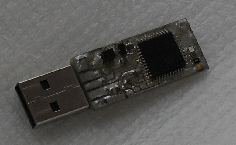
Features
-
Based on easily accessible microcontroller Microchip/Atmel xmega128A4U
-
single sided PCB
-
integrated CCID reader and card in one microcontroller
-
no driver needed for windows/linux - emulation of Gemalto reader
-
T0 and T1 protocol, TPDU exchange level
-
RSA speed: 2048 - about 10 second, 1536 about 5 seconds, 1024 about 1.7 seconds
-
ECC speed: secp384r1 about 2.5 seconds, prime256v1 about 1.1 seconds
-
low suspend current
-
two LEDs to signalize reader/card operation
-
optional button to approve sign/decrypt operations
-
full speed USB device with electrostatic discharge protection
(RSA speed tested on decrypt operation, time is difference between transmit ciphertext and receive decrypted data. The time may vary depending on the USB host.)
Drawbacks
Drawback are similar to OsEID card. But one significant drawback should be pointed up:
-
USB and CCID code in same microcontroller as card code reduces security of device (due complexity of code, bug in CCID/USB code can compromise card code and lead to getting private keys from card.
Components
1x ATMEL ATXMEGA128A4U-AU - microcontroller https://www.tme.eu/en/details/atxmega128a4u-au/8-bit-avr-family/microchip-atmel/
1x NXP PRTR5V0U2X.215 - ESD protection https://www.tme.eu/en/details/prtr5v0u2x.215/transil-diodes-arrays/nexperia/
1x MCP1700T3302E/TT LTO 3.3V - LDO stabilizer (quiescent current 1.6uA package SOT23) https://www.tme.eu/en/details/mcp1700t3302ett/ldo-unregulated-voltage-regulators/microchip-technology/mcp1700t-3302ett/
1x DL1206-4.7 4.7H - inductor package 1206 0.9ohm 50mA https://www.tme.eu/en/details/dl1206-4.7/smd-1206-inductors/ferrocore/dl1206-4r7/
1x DS1097-BN0 - USB connector https://www.tme.eu/en/details/usba-lp/usb-ieee1394-connectors/connfly/ds1097-bn0/
4x SMD capacitors in 1206 package (values from schematics) 4x SMD resistors in 1206 package (values from schematics) 2x SMD LED in 1206 package (red/green or red/blue)
1x Optional button OMRON B3U-3100PM https://www.tme.eu/en/details/b3u-3100pm/microswitches-tact/omron/
P2 connector is realized only by pads on PCB. Connector is used to program xmega by PDI programmer. Needle spring probe is used to connect programmer to P2 connector.
Programming
You need programmer that support PDI programming. One open source/open hardware can be found at:
To connect programmer to token, you need connector with spring needles (contacts pitch 2mm). Create a reduction from this connector to your PDI programmer. Use schematics of token and pin description of your programmer, to get correct connection. (P2 connector: 1st PIN to CPU is PDI, then RESET, + and GND). Make sure that programmer is set up to power device with 3.3V!
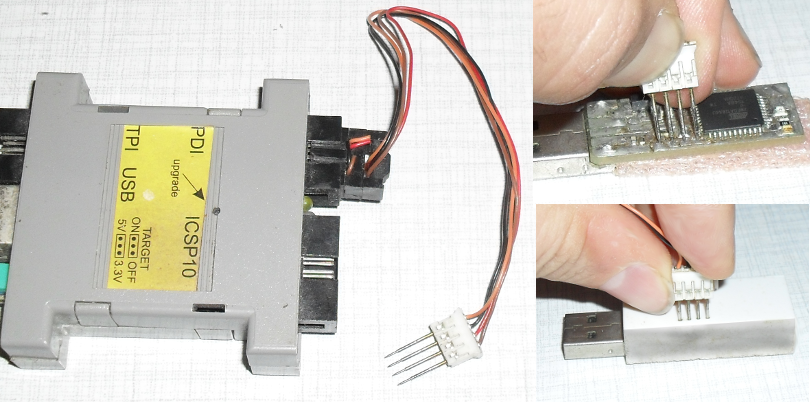
Example for avrdude and avrispmkII programmer:
$ avrdude -p x128a4u -c avrispmkII -e -v -U flash:w:download/OsEID_token.hex
$ avrdude -p x128a4u -c avrispmkII -v -U fuse2:w:0xBF:m
Compiling from sources
Compiling is similar to ATmega128 version:
make -f Makefile.xmega128a4u
make -f Makefile.xmega128a4u fuses
make -f Makefile.xmega128a4u program
Overclocking
Overclocking is not recommended, but if someone need this, there is a simple way to do this. CPU clock is defined in file targets/xmega128a4u/avr_os.c
// use PLL - multiply 2MHz RC oscillator to 32MHz
  OSC.PLLCTRL = OSC_PLLSRC_RC2M_gc | (32 / 2);
Overwrite multiplication factor (32 / 2) to requested value (for example (48 / 2)). Recompile and program your token.
There is lot of information about XMEGA overclocking on internet. Some people run XMEGA over 50MHz and more without any problems. Some other people report problems with EEPROM on overclocked XMEGAs. If your XMEGA burns, this is your problem. Please, read again disclaimer section in this manual.
Schematics

PCB
There exists two version of PCB, one for classical photographic method and etching in ferric chloride and second version for CNC routing. You can found OsEID_token.ngc file in download section. This file is designed for linuxcnc http://linuxcnc.org. Please read this file, adjust feed rate, check safe Z position, tune spindle commands, tool number etc. Dimensions in file are given in mm, make sure your machine uses metric, not imperial units. Use 0.3 up to 0.5mm milling tool. PCB is positioned at Z=-1, Z=1 is used for traverse. Run your machine without tool first!
AUTHOR IS NOT RESPONSIBLE FOR ANY DAMAGE OF YOUR MACHINE, TOOL OR ANY ANOTHER EQUIPMENTS. USE AT YOUR OWN RISK ONLY!


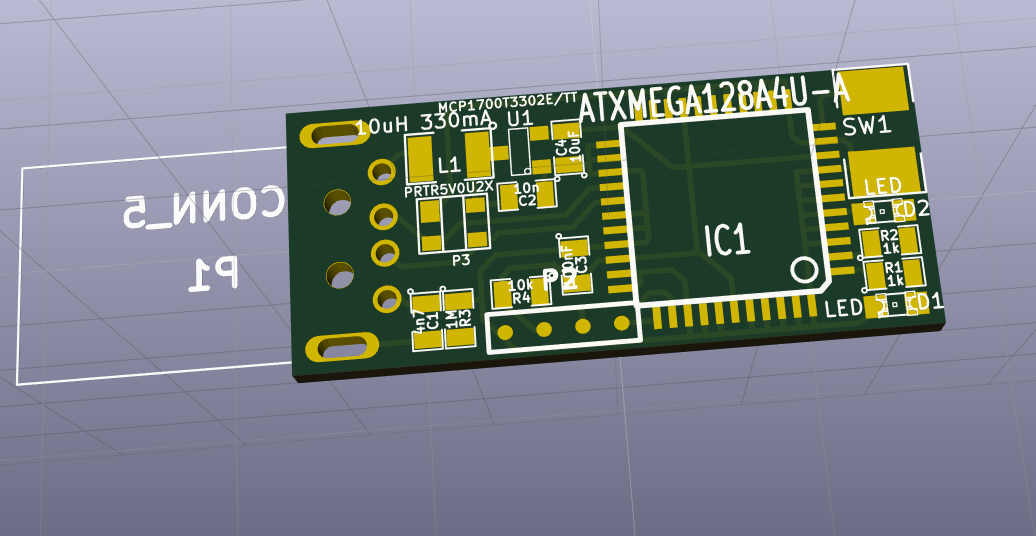
There is a plan for dual side PCB, with SD card reader. Development of this model is frozen for now.
Appendix E: AVR arithmetics
Addition, subtraction and rotate/shift operations
These operations are relatively simple, but to achieve desired speed, operations are partially unrolled. In one unrolled step 32 or 64 bit of operands are processed.
Multiplication
AVR multiplication is based on karatsuba multiplication. It uses modified open source (public domain) implementation from Michael Hutter and Peter Schwabe [AVR_KARATSUBA]. 256 bit multiplication code is fully revised to enable run in interrupt safe way (stack pointer change is protected by CLI instruction.) Code is faster, original code took 4797 clock cycles (in branched version), new code is about 6% faster and about 7% smaller. Similar changes are made in 192 bit multiplication.
The 128 bit multiplication is used only for 512 bit RSA. Because 512 bit key is not safe today, it makes no sense to waste lot of flash for this multiplication. Here simple looped code is used and this code is able to calculate truncated multiplication (low part of result) too. Another 128 bit multiplication (karatsuba based) is integrated inside truncated 256 bit multiplication.
operands size |
192 |
256 |
384 |
512 |
X 521 |
X 768 |
X 1024 |
clock cycles |
2854 |
4500 |
9986 |
15330 |
17568 |
33201 |
50276 |
xmega cycles |
2707 |
4283 |
- |
- |
- |
- |
- |
X - inclusive function call overhead (respect standard AVR ABI)
|
|
clock cycles are measured by simulavr. More info in targets/simulavr/Readme from OsEID tarball. |
|
|
clock cycles mentioned here are calculated for ATmega128. Xmega/AVR128DA can run faster, because memory store instructions (ST/PUSH) is running in one cycle - ATmega need two cycles here. |
Truncated multiplication speed
Result of this multiplication is in same length as operand length. Only low bits from result are available at end of this operation.
operands size |
128 |
192 |
256 |
384 |
512 |
clock cycles |
--- |
1625 |
2904 |
6558 |
10876 |
Squaring
192 and 256 bit squaring was written from scratch, it uses similar method as described in [AVR_SQUARING]. Code is designed as non branched. Squaring code is interrupt safe too.
operand size |
192 |
256 |
384 |
512 |
X 521 |
768 |
1024 |
clock cycles |
1839 |
3081 |
6532 |
10608 |
12855 |
21792 |
34713 |
xmega cycles |
1722 |
2883 |
- |
- |
- |
- |
- |
X - inclusive function call overhead (respect standard AVR ABI)
[AVR_SQUARING] is running in 1966/3253 clock cycles for 192/256 bit squaring.
Modular multiplicative inversion
Modular multiplicative inversion is based on left shift, similar to [Lorencz] or more similar to [Hars] shifting Euclidean algorithm. AVR microcontroller shift/rotate instruction allow us to rotate 8 bit value only by one bit in one instruction cycle. Original Hars algorithm is not usable without modifications (very slow repetitive rotations of V/S by f). The goal is to minimize the number of rotations.
In each step of algorithm U and V is aligned (by left rotations) on highest non zero bit, then this bit is eliminated by subtraction. R and S are kept updated similar to U and V. This step is repeating, but align is done by right rotation, until bit size of U is bigger that bit size of V. If this is not true, U and V (R and S) are swapped, and all rotations are returned back (right). This procedure is repeating until bit size of U is zero or one (no inversion exists or inversion found).
The U and V are represented as unsigned number, but there are helper variables sU and sV for storing the signs of U and V. R and S variables are signed (in range +- 1/2 of modulus). Final sign is determived from R sign and U sign.
C and AVR ASM version is available, but ASM version is not faster. Implementation allows us to calculate inversion for even modulus too (this is needed for calculation of CRT components). Code is designed to be small, the speed of the algorithm is not significant. (In versions before 20171231, right shift binary Euclidean algorithm was used, but this doesn’t allows us to calculate CRT components because modulus is always even number. This code is smaller as new code but is slower too.)
Modulo operation and modular reduction
Modulo operation
Up to the version 20190102 modulo operation uses binary division algorithm. The rotate/shift operation, as mentioned before, is slow on AVR devices, table of 8 rotated modulus values are used to save lot of rotate instructions. AVR assembler version of this code needs 262593 clock cycles for 1024 bit number (575021 clock cycles for 1536, 1008281 clock cycles for 2048). The code run in constant time.
To speed up this part of code, new code uses precalculated constant Bc. Reduction speed up is based on modified Barrett method described in [Hasenplaugh].
Let M be modulus of n bits length. Number N is to be reduced by M. Maximal bit length of N is 2n. Constant Bc of maximal bit length n is calculated from:
Bc = 21.5n mod M (1)
To calculate Bc binary division algorithm is used. Number N can be reduced to partial result number Rp (maximal bit length 1.5n+1):
Rp = N mod 21.5n + (N >> 1.5n) * Bc (2)
Calculating N mod 21.5n is not an extensive operation - low part of N up to 1.5n bits is a result of this operation. Rotation >> is not extensive too, upper 0.5n bits of N is a result of this operation. Multiplication with Bc uses two 0.5n bits multiplications.
Rp is then reduced to final R (R < M) by binary division algorithm but there is only 1+1.5n bits to reduce not 2n bits.
Only for completeness, there is some things that can be observed:
If number N is result of multiplication of two numbers A < M, B < M, and Rp of bit length 1+1.5n is result from (2), then result R < M can be computed by at most three subtractions of M << 0.5n from Rp
In RSA cryptosystem, prime P and Q has highest bit always set to 1 (i.e. 0x8001 for n=16, M in this calculation corresponds to P or Q). At most two subtraction of M << 0.5n is enough to reduce Rp to maximum 1.5n bits. This is also true for any A < 2n, B < 2n
Modular reduction inside RSA exponentiation
For commonly used Montgomery exponentiation we need to calculate two values: x1 = 1 * r mod M and x2 = msg * r mod M. Additionally we need precomputed constant Mc calculated from r * r-1 - M * Mc = 1. Here r is in form r = 2k. The smallest possible k is chosen so that r > N. "M' must be a odd number (M and r must be relatively prime).
For calculation of Mc modified Euclidean algorithm is used, where similar table for N is used as in modulo operation. Code is in AVR assembler, calculation needs only 188300 clock cycles for 512 bit modulus length (400684 clock cycles for 768 bit, 694988 clock cycles for 1024).
For calculating x1 = 1 * r mod n similar code can be used as for calculating x2 = msg * r mod n, but we can use special property of r to avoid division in this calculation ( [RSA_high_speed] page 48, chapter 3.8.1. claims need of division in this step ).
If n < 2k < 2 * n, then 2k mod n = 2k - n. Here negated n (0 - n) can be used directly as x.
Reduction steps to reduce N of size 2n bits to result Rp of maximal bit length n+1:
a = ((N mod 2n ) * Mc ) mod 2n (3)
b = a * N (4)
Rp = (N + b) >> n (5)
If Rp > M, one subtraction of Rp - M is sufficient to get result R < M.
OsEID used Montgomery reduction up to version 20190102. Newer version uses better method.
Because N can be reduced to Rp with bit length 1+1.5n by algorithm described above in modulo operation, only 0.5n bits from low part of Rp must be reduced by Montgomery reduction. This allows us to choose k as 1+0.5n. Calculation of x1 = 1 * r mod N is then eliminated, because 1 * r is always below N. Calculation of x2 is faster, only 1+1.5n must be reduced instead of 2n bits. Calculation of Mc is faster, we need only 0.5n bits.
Reduced Montgomery algorithm first calculates help variable a with bit size 0.5n from already reduced Rp by truncated multiplication (only low 0.5n bits are used):
a = ((Rp mod 20.5n) * Mc) mod 20.5n (3*)
For reducing Rp we need to calculate number b which is added to Rp and this addition zeroize low 0.5n bits in Rp
b = a * N (4*)
Computing b cost only two half sized (0.5n) multiplications. Finally result R is calculated:
R = (Rp + b) >> (0.5n) (5*)
Maximal bit length of R is 2+n bits and to reduce this to bit length not greater that n up to two subtractions of N is needed. Of course, result R is in Montgomery form and it is not necessarily that R < M.
To get final result after exponentiation, one more step is needed - multiplication by 1 and Montgomery reduction. This reduction always need at maximum one subtraction of M to guarantee final result R < M.
Old code uses three 0.5n sized multiplications in Karatsuba multiplication, then one 0.5n sized multiplication and two 0.5n sized truncated multiplications are used to construct one n sized truncated multiplication.
New code need only 0.5n sized truncated multiplications and four 0.5n sized multiplications.
Old and new code need some overhead for additions and subtractions. Finally, old code with full sized Montgomery reduction for reducing 1024 bit to 512 bit need about 27000 clock cycles. New code needs only 24300 clock cycles.
Maybe this algorithm reminds someone of so-called bipartite Modular multiplication but there is difference in reduction of upper bits. Bipartite method uses some multiply of n to reduce upper part of N. This code is different, there is no multiply of n added to N.
Someone may ask, why there is not used Barrett folding as described in [Hasenplaugh]. This method need multiplication of operands with 1+0.5n and 0.5n size. Even this can be calculated with normal 0.5n multiplication and some addition (using the AND instruction for one more bit in operand), it will introduce more overhead as in explained algorithm. Then there is 1+n and n operand size in final part of folding, this introduce second overhead. It can be guessed, that currently implemented algorithm is faster (on 8 bit AVR platform).
ECC operation speed
EC calculation uses projective coordinates. Lot of code is inspired by NIST [NIST_ECC] and [OPENCRYPTOTOKEN] EC point doubling is optimized for NIST curves and for secp256k1 curve. EC point multiplication is designed as constant time, with multiplication window of 4 bits. Point multiplication is blinded. For each supported curve, a separate fast reduction algorithm is used. The secp521r1 curve is supported only on devices with 8KB RAM and more (AVR128DA, xmega128A4U). Firmware for atmega128 microcontroller can be recompiled with two bits multiplication window, then secp521r1 is running on this device.
window 4 |
window 2 |
|||
32 bit blinding |
not blinded |
32 bit blinding |
not blinded |
|
prime192v1 |
15,5 |
13,5 |
19,0 |
----- |
prime256v1 |
38,7 |
34,6 |
48,7 |
----- |
secp256k1 |
---- |
47,1 |
---- |
----- |
secp384r1 |
82,9 |
76,8 |
106,1 |
----- |
secp521r1 |
140,9 |
133,8 |
182,5 |
----- |
RSA operation speed
In the next table, there is RSA calculation timing in clock cycles (normal RSA / precalculated constants for modulo and P-1 mod R and Q-1 mod R in key file), interrupt always enabled. Exponentiation window is not optimal to any key size - optimal window for key size 512/768 is 4 bits, not 5, but code uses fixed size defined at compilation time (based on RAM size of device) for all key sizes. Because 512/768 bit key is not safe today, it makes no sense to optimize 512/768 bit calculation for window size 5 bits.
no blinding |
precalc, blinding |
||||
key size |
window |
precalc |
no precalc |
Bellcore.prot |
|
512 |
2 |
16,17 |
16,81 |
18,22 |
19.01 |
4 |
14,29 |
14,43 |
15,57 |
16,35 |
|
5 |
14,61 |
14,75 |
15,87 |
16,66 |
|
768 |
2 |
27,47 |
27,67 |
29,17 |
30,01 |
4 |
23,08 |
23,38 |
24,48 |
25,32 |
|
5 |
22,97 |
23,26 |
24,61 |
25,44 |
|
1024 |
2 |
57,16 |
57,66 |
59.83 |
61,14 |
4 |
47,81 |
48,32 |
50,01 |
51,32 |
|
5 |
47,29 |
47,79 |
49,45 |
50,75 |
|
1536 |
2 |
178,4 |
179,5 |
184,0 |
186,7 |
4 |
147,8 |
148,9 |
152,4 |
155,1 |
|
5 |
144,4 |
145,5 |
148,9 |
151,6 |
|
2048 |
2 |
365,7 |
367,6 |
374,3 |
378,5 |
4 |
302,7 |
304,6 |
309,7 |
313,9 |
|
5 |
293,8 |
295,7 |
302,1 |
306,4 |
|
To reach this, lot of assembler routines are used, especially Montgomery algo and function like mul256 mod 2256 (truncated multiplication). To get best possible performance, the 384, 512, 768 and 1024 bit squaring and multiplication are unrolled as possible, with respect to flash memory size in AVR.
Code size: about 20 000 lines in AVR assembler, about 10000 lines in C. AVR flash in ATmega128 is occupied by ~ 63kB code, 64Kb is used as data space for card filesystem. RAM is almost full, there is approximately 80 bytes free in atmnega128 (4kB RAM space).
Appendix F: Cryptographic algorithm security
RSA security
OsEID implements several protections to generally known attacks to RSA cryptosystem. There exists several types of side channel attacks:
Simple Power Analysis (SPA) / timing attack
To prevent this type of attack, OsEID uses:
-
constant time calculation (time does not depend on key or message value)
-
Exponentiation uses fixed window size, window is not sliding, zeros are not skipped.
RSA implementation in OsEID card is resistant to SPA / timing attack.
Differential Power Analysis (DPA)
To prevent this type of attack, OsEID uses:
-
card uses exponent blinding
In default settings 24 bits random value is used to blind private exponent parts (dP and dQ). Exponent blinding is a big barrier for lot of advanced techniques that allow use of side channel attack to expose private keys.
-
Card does not support message blinding [RSA_MSG_BLINDING]
Due constant time of operation (no variable length sliding window), it is not possible to use known attacks which could work due to the absence of a message blinding.
-
Card does not support modulus blinding
Modular reduction is needed to calculate Montgomery product like 1 * r mod n and M * r mod n. In both cases, n is secret value P or Q. Due CRT calculation there are operations like M mod P and M mod Q. Modular reduction is running in constant time, but is not blinded. There is a way to extract power fingerprint from this operation. It is necessary to run lot of power traces to get reliable power fingerprint from the same message. Several special formatted messages must be traced to get some information about P/Q. Because number of analyzed messages run over 30 000, this type of attack is not realistic for now. More about this attack to this function can be found in [DPA_on_modular_reduction].
Because missing message blinding, there is another point that allow extract some information from card. CRT recombination (Garner`s algorithm) produce result, that need conditional addition. This addition is always realized, but power trace can be used to detect which of two possible results is used as return value. It’s not easy to detect this step in one power trace, but the correlation of a very large number of power traces may leak some information about this step.
Montgomery product needs n' from equation r* r^-1 - n * n' = 1. This calculation is running in constant time, but is not blinded. There is a way to use DPA for extracting some information about P and Q from card. In default firmware configuration, this calculation is running only in key upload operation, therefore the security of this algorithm is for now irrelevant.
RSA implementation in OsEID card is (reasonably) resistant to DPA attack
Algorithm problem
RSA implementation uses [CRT] (China Remainder Theorem). [SINGLE_ERROR] in CRT implementation can expose private key. This is also known as [BELLCORE] attack. To prevent this type of attack, OsEID uses:
-
result of exponentiation is checked by public exponent.
This extends the calculation time by approximately 2% for 2048 bits to 5% for 512 bits RSA. CRT recombination is not protected, but injecting fault precisely into this point is very difficult. Implementing full check (exponenting signature by public exponent) is problematic due RAM and FLASH size limitation. There is not protection against wrong loaded P or Q from key storage! There is about 10 msec interval for 1024 bit key for injecting error in message mod P/Q calculation and about 38 msec if 2048 bit key is used. Intervals for OsEID token are about 2.5x shorter.
There is lot of methods to inject error into microcontroller calculation, fotons from laser/flash light can be used or some particle from radioactive isotope or electrostatic discharge etc. Is very difficult to hit exact time and exact part of microcontroller (for example do not hit program counter but hit only some of registers or ALU, exact part of RAM etc.), lot of attempt is needed and lot of luck is needed. Usually any of attempts ends with halted microcontroller or in worst case with total damage of microcontroller.
RSA implementation in OsEID card is (reasonably) resistant to Bellcore attack
RSA key generation
OsEID supports RSA key generation. This operation is really slow, but is not subject to [ROCA]. There is really random prime selection algorithm used for RSA key generation.
Number from random generator is modified - highest and lowest bit are set to 1 and this number is then tested by simple sieve - division by 1st 130 primes - and then Miller-Rabin test is used as primality test. There is no hardware divisor in AVR devices, GCD is used to check all 130 primes in one step (product of 1st 130 primes can be fitted into 1024 bit value, this value is one operand in GCD, second operand is tested number).
Number is considered to be a prime number if pass the Rabin-Miller test. Rabin-Miller test consider number to be a prime after several loops with different parameter A. Number of loops is based on length of a tested prime. (Listed in row "MR loop pass").
key size |
512 |
768 |
1024 |
1536 |
2048 |
prime size |
256 |
384 |
512 |
768 |
1024 |
total primes generated |
33600 |
33164 |
32964 |
33082 |
33216 |
rejected, small product P * Q |
6551 |
6312 |
6213 |
6300 |
6350 |
rejected P,Q too close |
249 |
270 |
269 |
238 |
258 |
average GCD op. for one prime |
73.83 |
110.64 |
146.83 |
222.95 |
295.65 |
average MR op. for one prime |
13.97 |
22.53 |
28.87 |
44.7 |
59.18 |
MR loop pass |
12 |
8 |
6 |
4 |
3 |
When both primes are found, they are tested if they are not too close to each other. Then modulus is calculated, and tested if modulus is not too short (if highest bit is not set - short modulus). Finally RSA components are calculated. If some of test fails, both primes are discarded and two new primes are searched. This handling prevents unnecessary bias of prime/modulus value.
Most often, we need to generate 4 primes (only 33% probability to generate good P,Q who are not rejected due small product P*Q or P,Q is too close together).
key size (bits) |
512 |
1024 |
2048 |
prime size (bits) |
256 |
512 |
1024 |
clock cycles |
1.7 |
2.0 |
2.4 |
time - card (seconds) |
0.063 |
0.076 |
0.089 |
time - token (seconds) |
0.054 |
0.063 |
0.075 |
For one prime (512 bit) we need in average 147 GCD operations, total time 147*0.076 = about 11 seconds. Then 29+6 Miller-Rabin test (one about 1 sec) = about 35 seconds. For one prime we need in average 46 seconds.
Generation of 1024 bit key (4 primes ) then take in average about 3 minutes, but in worst case over 15 minutes.
When generating a 2048 bit key you have to be very patient. Count with time 0.5 to 1.5 hours. (One Miller-Rabin test run in about 5.5 second - there is really no way to run this faster with only one 8 bit multiplier in AVR)
Keep in mind, if you generate a key, operation is not blinded. Exponentiation in Miller-Rabin test, squaring, and CRT components calculation (3x modular multiplicative inverse) is not blinded too. SPA, DPA or IPA can be used to extract some informations about generated key. Therefore it is recommended to generate key only in secure environment, if key security is important.
OsEID project does not use strong primes for P and Q. Strong primes can protect us from factorization of modulus using Pollard’s algorithm, but strong primes do not protect us against new methods of modulus factorization for example Lenstra elliptic curve factorization or Number Field Sieve.
RSA key generation is not resistant to side channels attack
Please read more about [RSA_attack_resistance], OsEID is hobby card, you can not expect perfect resistance to all attacks.
ECC security
Briefly, all implemented curves are not secure enough, more info at [SAFECURVES]. Apart from this information, implemented elliptic curves are widely used on the Internet. If you have any doubts about the safety of NIST curves, please search internet about rigidity of NIST curves. Some information can be found here: [NIST_RIGGED]
To prevent SPA, EC calculation is running in constant time (but not perfect constant time, for example, modular multiplicative inversion run time depends on input numbers). OsEID implementation also uses blinding in point multiplication. Random 32 bit value is used to blind private key in point multiplication. SPA attack is not very effective. Still DPA/IPA can be used to extract some of sensitive information from other functions. It is, however, much more problematic as the attack on not blinded point multiplication.
Card firmware implementation may also have some security bugs. You have been warned.
(Do you know about these shortcomings in the world of commercial cards?)
Appendix G: Literature
sorry, no paper literature, only internet links
Card/ISO7816 related literature
AVR
atmega128
Mathematics implementations in AVR
Modular Multiplicative Inversion
ECC
-
[NIST_ECC] http://citeseerx.ist.psu.edu/viewdoc/download?doi=10.1.1.204.9073&rep=rep1&type=pdf (https://apps.nsa.gov/iaarchive/library/ia-guidance/ia-solutions-for-classified/algorithm-guidance/mathematical-routines-for-the-nist-prime-elliptic-curves.cfm)
-
[SAFECURVES] https://safecurves.cr.yp.to/
-
[NIST_RIGGED] https://crypto.stackexchange.com/questions/12898/is-there-a-feasible-method-by-which-nist-ecc-curves-over-prime-fields-could-be-i
RSA
-
http://citeseerx.ist.psu.edu/viewdoc/download?doi=10.1.1.538.4909&rep=rep1&type=pdf
-
[RSA_high_speed] ftp://ftp.rsasecurity.com/pub/pdfs/tr201.pdf
-
https://www.nics.uma.es/pub/seciot10/files/pdf/liu_seciot10_paper.pdf
-
[RSA_MSG_BLINDING] https://eprint.iacr.org/2014/869.pdf
-
https://www.cryptoexperts.com/ches2015/slides/day2/session1/talk2.pdf
-
[SINGLE_ERROR] https://www.cryptologie.net/article/371/fault-attacks-on-rsas-signatures/
-
[BELLCORE] https://eprint.iacr.org/2012/553.pdf
-
[DPA_on_modular_reduction] https://link.springer.com/content/pdf/10.1007/3-540-36400-5_18.pdf
-
[RSA_attack_resistance] https://www.bsi.bund.de/SharedDocs/Downloads/DE/BSI/Zertifizierung/Interpretationen/AIS_46_BSI_guidelines_SCA_RSA_V1_0_e_pdf.pdf
-
[Hasenplaugh] https://www.lirmm.fr/arith18/papers/hasenplaugh-FastModularReduction.pdf
RNG
USB related literature/software
CCID
MyEID
Related projects
minidriver
Licence
Appendix H: OpenSC patches
OpenSC 0.20 and 0.21
Card is automatically detected. No patch is needed. If you need support for secp256k1, please read about experimental support for secp256k1 below.
OpenSC 0.17, 018 and 0.19
OpenSC 0.17, 0.18 and 0.19 can detect all features of OsEID except of support for secp256k1. To use myeid driver for OsEID card you need to configure OpenSC package only. Please insert OsEID ATR into opensc.conf file.
Experimental support for secp256k1
OpenSC can signalize support for secp256k1 curve. For OpenSC 0.17, 0.18 and 0.19 following patch is suggested:
--- opensc-0.17rc1/src/libopensc/card-myeid.c.orig     2017-06-13 13:23:53.000000000 +0200
+++ opensc-0.17rc1-patched/src/libopensc/card-myeid.c  2017-06-20 08:58:43.650806261 +0200
@@ -79,6 +79,7 @@
        "3B:89:80:01:09:38:33:B1:4D:79:45:49:44:4C",
        "3B:F5:96:00:00:80:31:FE:45:4D:79:45:49:44:15", /* Infineon's chip */
        "3B:F5:96:00:00:81:31:FE:45:4D:79:45:49:44:14",
+       "3B:F5:18:00:02:10:80:4F:73:45:49:44",          /* OsEID */
+       "3B:F5:18:00:02:80:01:4F:73:45:49:44:1A",       /* OsEID token*/
        NULL
 };

@@ -113,6 +114,7 @@
        {"secp384r1", {{1, 3, 132, 0, 34, -1}},         384},
        {"secp521r1", {{1, 3, 132, 0, 35, -1}},         521},
        {NULL, {{-1}}, 0},
+       {"secp256k1", {{1, 3, 132, 0, 10, -1}},         256},   /* OsEID */
 };

 static int myeid_get_info(struct sc_card *card, u8 *rbuf, size_t buflen);
@@ -227,6 +229,9 @@
                if (card_caps.max_aes_key_length >= 256)
                        _sc_card_add_symmetric_alg(card, SC_ALGORITHM_AES, 256, flags);
        }
+        /* OsEID support for secp256k1 */
+        if (0 == memcmp("OsEID", card->atr.value + card->atr.len - 5, 5))
+               _sc_card_add_ec_alg(card,  ec_curves[5].size, flags, ext_flags, &ec_curves[5].curve_oid);
+        if (0 == memcmp("OsEID", card->atr.value + card->atr.len - 6, 5))
+               _sc_card_add_ec_alg(card,  ec_curves[5].size, flags, ext_flags, &ec_curves[5].curve_oid);

        /* State that we have an RNG */
        card->caps |= SC_CARD_CAP_RNG | SC_CARD_CAP_ISO7816_PIN_INFO;
With this patch you can upload secp256k1 key into card. You can generate key by openssl and upload to card by standard opensc tool:
pkcs1515-init --store-private-key key.pem
There is no simple way to decide what curve is used (secp256k1/secp256r1) in card firmware/OpenSC. Original MyEID card does not support curve OID specification in key upload/key generate functions. It is not simple to design a reasonable method for specifying curve OID, which does not affect compatibility with newer versions of MyEID card. For now, filetype 0x23 is used to mark secp256k1 internal key file.
After uploading secp256k1 key, you need to determine key file path (use pkcs15-tool -D command). Then change type of this file. For this purpose proprietary APDU can be used. This proprietary APDU is a special variant of PUT DATA command, but with CLA code 0x80:
0x80 0xDA 0x00 0x00 0x00
Before use of this APDU, SELECT and VERIFY command must be issued on key file. (Key file path can be determined by pkcs15-tool -D command)
Please read OsEID-tool script for example usage.
Card can generate secp256k1 key, but this needs more patches in OpenSC (before key is generated, key file must be created with 0x23 value in tag 0x82). Unfortunately, there is no curve type information available in this part of OpenSC (ver 0.16.0) code and there is no simple way to determine what curve is to be used (secp256k1/prime256v1).
To test key generation, there is a simple way - recompile OpenSC to always generate 0x23 value in tag 0x82 for EC keys.
--- opensc-0.16.0/src/libopensc/cardctl.h       2016-05-31 09:36:09.000000000 +0200
+++ opensc-0.16.0-patched/src/libopensc/cardctl.h       2016-12-13 13:19:23.461149289 +0100
@@ -856,7 +856,7 @@
  */
        enum SC_CARDCTL_MYEID_KEY_TYPE {
                SC_CARDCTL_MYEID_KEY_RSA = 0x11,
-               SC_CARDCTL_MYEID_KEY_EC  = 0x22
+               SC_CARDCTL_MYEID_KEY_EC  = 0x23
        };

        struct sc_cardctl_myeid_data_obj {
After generating secp256k1 key, recompile OpenSC with original libopensc/cardctl.h, and load/generate rest of normal (NIST) EC keys, RSA keys etc.
Appendix I: Random generator implementation
There is very simple random generator used in all devices (AVR128DA32, ATmega128 and xmega). There is no seed, no hash function, no reseed function.
AVR128DA32 and Xmega uses 12 bit ADC to measure internal temperature sensor.
AVR128DA32 internal band gap is usable only if supply voltage is over 2.5V. Because card is able to run in reader with supply voltage 1.8V, no band gap but input supply voltage is used as reference for ADC.
xmega128a4u uses internal band gap as reference for ADC.
Only bit 0 from ADC conversion is used as entropy value.
Generator tests by ent software from http://www.fourmilab.ch/random/ (This tests are made with small data blocks, random generator quality is here well demonstrated - RSA key generation and ECC cryptography uses small data blocks)
Even AVR128DA32 and xmega128a4u use different reference voltage for ADC, both implementations show approximately identical results.
File parsed as the bit stream:
==============================
Entropy = 1.000000 bits per bit.

Optimum compression would reduce the size
of this 83264 bit file by 0 percent.

Chi square distribution for 83264 samples is 0.04, and randomly
would exceed this value 75.00 percent of the times.

Arithmetic mean value of data bits is 0.5003 (0.5 = random).
Monte Carlo value for Pi is 3.155709343 (error 0.45 percent).
Serial correlation coefficient is -0.000145 (totally uncorrelated = 0.0).

File parsed as the byte stream:
===============================
Entropy = 7.981877 bits per byte.

Optimum compression would reduce the size
of this 10408 byte file by 0 percent.

Chi square distribution for 10408 samples is 258.70, and randomly
would exceed this value 50.00 percent of the times.

Arithmetic mean value of data bytes is 127.4115 (127.5 = random).
Monte Carlo value for Pi is 3.155709343 (error 0.45 percent).
Serial correlation coefficient is 0.001352 (totally uncorrelated = 0.0).
The result is excellent for such a simple generator.
Unfortunately, similar result is not available on atmega128 with 10 bit ADC. There is no temperature sensor. ADC is set to measure input voltage (to internal band gap reference). Only bit 0 from ADC conversion is used as entropy value.
Result of this RNG is not good. Random generator is strongly affected by input voltage characteristics (this depends on card reader, USB host, cables, external interference etc..). For example, in some environments random generated data are significantly biased - arithmetic mean value over 160 or higher, Monte Carlo value for PI below 0.1, Chi square never exceed 0.01 percent, etc… In some other environment RNG data are relatively good, but still Chi square is wrong.
To get better result, DES cipher is used on 16 bytes from ADC random data (8 bytes data, 8 bytes key) and resulting 8 bytes from DES cipher xored with key are used as return value from RNG.
In next tables results for OsEID token/card and MyEID card can be compared. (Beware, in this table, result for atmega generator without DES is one of the good ones /one of the best, but still with very wrong chi square value)
Small data set 10408 bytes:
| xmega | atmega | atmega+DES | MyEID 3.3.3 | |
|---|---|---|---|---|
Entropy per bit |
1.000000 |
0.999766 |
0.999993 |
0.999997 |
Entropy per byte |
7.981877 |
7.781246 |
7.982590 |
7.982021 |
Chi square (bit stream) |
75.00 |
0.01 |
50.00 |
54.64 |
Chi square (byte stream) |
50.00 |
0.01 |
50.00 |
38.19 |
Arithmetic mean (bit) |
0.5003 |
0.5090 |
0.5016 |
0.5010 |
Arithmetic mean (byte) |
127.4115 |
123.8805 |
128.1469 |
127.4539 |
Serial correlation (bit) |
-0.000145 |
0.111164 |
0.004077 |
0.000332 |
Serial correlation (byte) |
0.001352 |
0.046713 |
-0.009899 |
0.005033 |
Monte Carlo value for Pi |
3.155709343 |
3.158016148 |
3.106751298 |
3.111367571 |
Big data set (about 100 MBytes):
| xmega | atmega+DES | |
|---|---|---|
Entropy per bit |
1.000000 |
1.000000 |
Entropy per byte |
7.999998 |
7.999998 |
Chi square (bit stream) |
41.54 |
78.08 |
Chi square (byte stream) |
41.47 |
23.43 |
Arithmetic mean (bit) |
0.5000 |
0.5000 |
Arithmetic mean (byte) |
127.5091 |
127.4966 |
Serial correlation (bit) |
0.000010 |
0.000017 |
Serial correlation (byte) |
-0.000078 |
-0.000194 |
Monte Carlo value for Pi |
3.140210247 |
3.141706616 |
More tests with big data sets (100MB) were made by dieharder software (http://www.phy.duke.edu/~rgb/General/dieharder.php).
(In doc directory you can found output from dieharder software for card and token RNG.)
Random generator speed
Speed measurement is only approximate, speed depend on card reader, 3.8MHz reader was used. USB utilization also have an impact on speed tests.
| AVR128DA32 | xmega | atmega | atmega+DES | MyEID 3.3.3 | |
|---|---|---|---|---|---|
240 bytes in APDU |
772 bytes/sec |
4661 bytes/sec |
1346 bytes/sec |
640 bytes/sec |
2670 bytes/sec |
32 bytes in APDU |
460 bytes/sec |
750 bytes/sec |
340 bytes/sec |
225 bytes/sec |
340 bytes/sec |
Note: OsEID card uses T0 protocol, MyEID and OsEID token use T1 protocol.
Appendix J: Card simulator
All card functions can be tested without any hardware. Card simulation is then running as one task in OS. Simulation is attached to pseudoterminal. This pseudoterminal is then connected to simulated card reader, and this reader is attached to pcscd. Simulation creates one file card_mem, where it maintains the FLASH and EEPROM memory of card.
For now, this simulator must run with root privileges. Consider this before running this on your computer. You need socat package to run simulation. This simulation is tested on DEBIAN 9 and DEBIAN 10 system.
[OpenSC] project uses this simulation for CI tests on https://travis-ci.org/, here simulation is running on Ubuntu bionic. For details about this CI test please read https://github.com/OpenSC/OpenSC/blob/master/.travis.yml
Steps to use:
1. Unpack OsEID tarball
2. cd src
3. make -f Makefile.console
4. su / sudo to get root
5. systemctl stop pcscd.socket
6. systemctl stop pcscd.service
7. build/console/run_pcscd.sh
8. switch to another window/console
9. pcsc_scan
If card is available, You can use OsEID-tool to test functionality of card (OsEID-tool is in tool directory included in tarball)
./OsEID-tool INIT
./OsEID-tool RSA-CREATE-KEYS
./OsEID-tool RSA-UPLOAD-KEYS
pkcs15-tool -D
./OsEID-tool RSA-DECRYPT-TEST
WARNING! all other readers in system are available to pcscd too, please disconnect all other readers or remove another cards from reader to prevent unwanted modification of your real card.
Better (but slower) simulation uses simulavr. This allow us to test card functionality inclusive ASM routines for AVR, measuring speed of procedures and debugging card function in native AVR instructions. Please read targets/simulavr/Readme from OsEID tarball.
Appendix K: DES and AES implementation
Both ciphers are optimized to minimal flash size. Of course, the code is written in assembler, but C version is available to. Both ciphers are optimized to run on 8 bit AVR microcontroller. Xmega microcontroller already contains DES instruction, but due absence of this instruction in atmega, both microcontrollers uses same code (without special DES instructions). Xmega contains accelerated engine for 128 bit AES. This is not used for the same reason - atmega does not contain this accelerator. Limiting AES to 128 bit is another reason to do not use xmega accelerator.
Both ciphers are designed to run in constant time (time does not depend on message or key bits). Timing attack is protected, but differential power attack is not protected. (similar problem is in XMEGA accelerated engine: https://www.cryptolux.org/images/7/7b/Xmegarump.pdf, https://wiki.newae.com/Tutorial_A6_Replication_of_Ilya_Kizhvatov%27s_XMEGA%C2%AE_Attack or location dependent EM leakage, please search internet for this keywords).
DES
Code is modified, does not use standard permutations as described by DES original (NIST) description.
Message expansion (E), Permuted choice 1 (PC-1) and Permuted choice 2 (PC-2) are merged into one 56 bit long message expansion. This expanded message is directly XORed by plain key. S-box addresses are selected from result of XOR operation by table. S-boxes are merged to one table (256 bytes).
Initial and inverse initial permutation is done by procedures. Key expansion is in procedure too. Only the permutation (P) is unchanged.
Code is really small, 800 bytes for DES or 828 bytes if 3DES is needed. Speed about 50 000 clock cycles for DES decipher or encipher.
More informations can be found in C and ASM sources.
AES
AES supports key sizes 128/192/256 bits. AES code is extra small, below 600 bytes. S-BOX is calculated into RAM. About 800 bytes of RAM is needed (for S-box, inverse S-box and expanded key). Code is compact, does not use context and therefore the S-box must be calculated repeatedly for every run of AES. Speed is sufficient, about 40 000 clock cycles for one AES encipher or decipher with 256 bit key.
Appendix L: Application setup
openssh
Insert path to pkcs11 library into .ssh/config file:
PKCS11Provider /usr/lib/x86_64-linux-gnu/opensc-pkcs11.so
openvpn
Insert path to pkcs11 library into openvpn config file:
pkcs11-providers /usr/lib/x86_64-linux-gnu/opensc-pkcs11.so
Determine serialized ID of your card/token:
openvpn --show-pkcs11-ids /usr/lib/x86_64-linux-gnu/onepin-opensc-pkcs11.so
Copy Serialized id from previous command output, and insert this into your openvpn config file:
pkcs11-id ' --- here serialized id — '
If you use RSA key, you can hit a error:
2020-10-12 16:41:13 us=348869 OpenSSL: error:141F0006:SSL routines:tls_construct_cert_verify:EVP lib 2020-10-12 16:41:13 us=348892 TLS_ERROR: BIO read tls_read_plaintext error 2020-10-12 16:41:13 us=348907 TLS Error: TLS object → incoming plaintext read error 2020-10-12 16:41:13 us=348921 TLS Error: TLS handshake failed 2020-10-12 16:41:13 us=349019 Fatal TLS error (check_tls_errors_co), restarting
In this case please upgrade: openvpn to version 2.5-rc2 libpkcs11-helper1 to version 1.26
chromium
-
exit chromium
-
in command promt (if modutil is missing, please install libnss3-tools package):
$ cd
$ modutil -dbdir sql:.pki/nssdb/ -add "opensc" -libfile  /usr/lib/x86_64-linux-gnu/opensc-pkcs11.so
-
check configuration:
$ modutil -dbdir sql:.pki/nssdb/ -list
-
start chromium
apache 2.4.37(38) setup
secured directory /var/www/html/SSL_AUTH_TEST/
insert into /etc/apache2/sites-available/default-ssl.conf
SSLVerifyClient none
SSLVerifyDepth 1
SSLCACertificateFile "/var/www/html/SSL_AUTH_TEST/ca.crt"
SSLOCSPResponderTimeout 60
SSLProtocol TLSv1.2

<Location "/SSL_AUTH_TEST">
SSLVerifyClient require
SSLVerifyDepth 1
SSLRequire %{SSL_CIPHER_USEKEYSIZE} >= 80
</Location>
Do not use TLSv1.3 here, firefox/chromium fails here with message: "Cannot perform Post-Handshake Authentication."
This appendix is only partial, please read on internet for example:
Appendix M: RSA calculation in genius
This part of doc is only for explanation how RSA cryptosystem works. Especially, here is explained how message and exponent blinding can be implemented and how can single error in CRT calculation expose P and Q.
To run calculation from this appendix, please use genius calculator available from http://www.jirka.org/genius.html. Code from this appendix can be pasted directly into genius console. To track calculation, do not paste whole code at once, code is divided by lines with asteriskses, paste only partial code and check results in genius console.
# This is part of OsEID project documentation,
# https://sourceforge.net/projects/oseid/
.
#
#
# key calculation: choice prime numbers p,q, calculate totient
# ------------------------------------------------------------
.
p = 251
q = 337
totient = (p - 1) * (q - 1)

# choice public exponent
# most commonly used public exponent is 65537
# --------------------------------------------------------
.
pub_exp = 65537

# calculate private exponent
# --------------------------
.

priv_exp = pub_exp ^ -1 mod totient
# calculate n
n = p * q

# calculate  CRT components
# ------------------------
.
dP = (pub_exp^-1) mod (p-1)
dQ = (pub_exp^-1) mod (q-1)
qInv = q ^ -1  mod p

# encipher and decipher
# ---------------------
.
msg = 41444
ciphertext = msg ^ pub_exp mod n
plaintext = ciphertext ^ priv_exp mod n

#
# if calculation is correct, plaintext is 41444
# *****************************************************************
.

# decipher with message blinding
# ------------------------------
.
blind_msg_rnd = 54       # random number

blind_cipher_msg_rnd = blind_msg_rnd ^ pub_exp mod n
blind_cipher         = blind_cipher_msg_rnd * ciphertext mod n
blind_plain          = blind_cipher ^ priv_exp mod n

blind_msg_rnd_inv = blind_msg_rnd ^ -1 mod n
plaintext         = blind_msg_rnd_inv * blind_plain mod n

#
# if calculation is correct, plaintext is 41444
# *****************************************************************
.

# decipher with exponent blinding
# -------------------------------
.
blind_exp_rnd = 56      # random number

blind_exp = blind_exp_rnd * totient + priv_exp
plaintext = ciphertext ^ blind_exp mod n

#
# if calculation is correct, plaintext is 41444
# *****************************************************************
.

# CRT decipher
# ------------
.
cipher_m1 =  ciphertext mod p
cipher_m2 =  ciphertext mod q

m1 = cipher_m1 ^ dP mod p
m2 = cipher_m2 ^ dQ mod q
h = qInv * (m1 - m2) mod p
plaintext = m2 + h * q
#
# if calculation is correct, plaintext is 41444
# *****************************************************************
.

# CRT single error explanation:
# -----------------------------
# calculation of m2 fail:
.
m2 = 123
h = qInv * (m1 - m2) mod p
plaintext = m2 + h * q
# failed plaintext is used to reconstruct 'p'
# -------------------------------------------
.
reconstructed_p = gcd (plaintext - msg, n)
reconstructed_q = n / rp
#
# if calculation is correct, 'p' = 251 and 'q' = 337
# message blinding or exponent blinding does not eliminate single error!
# *****************************************************************
.
# CRT decipher with message blinding
# ----------------------------------
cipher_m1 =  ciphertext mod p
cipher_m2 =  ciphertext mod q

blind_msg_rnd = 54     #random number

blind_msg_p = blind_msg_rnd ^ pub_exp mod p
blind_cipher_p = blind_msg_p * cipher_m1
blind_cipher_m1 = blind_cipher_p mod p

blind_msg_q = blind_msg_rnd ^ pub_exp mod q
blind_cipher_q = blind_msg_q * cipher_m2
blind_cipher_m2 = blind_cipher_q mod q

blind_m1 = blind_cipher_m1 ^ dP mod p
blind_m2 = blind_cipher_m2 ^ dQ mod q

blind_inv_msg = blind_msg_rnd ^ -1 mod n

blind_inv_msg_p = blind_inv_msg mod p
m1 = blind_m1 * blind_inv_msg_p mod p

blind_inv_msg_q = blind_inv_msg mod q
m2 = blind_m2 * blind_inv_msg mod q

h = qInv * (m1 - m2) mod p
plaintext = m2 + h * q
#
# if calculation is correct, plaintext is 41444
# *****************************************************************
.

# similar, but unblinding after recombination:
.
h = qInv * (blind_m1 - blind_m2) mod p
plaintext_blindend = blind_m2 + h * q
plaintext = plaintext_blindend * blind_inv_msg mod n

#
# if calculation is correct, plaintext is 41444
# *****************************************************************
.

# CRT decipher with message and exponent blinding
# -----------------------------------------------
cipher_m1 =  ciphertext mod p
cipher_m2 =  ciphertext mod q

blind_msg_rnd = 54

blind_msg_p = blind_msg_rnd ^ pub_exp mod p
blind_cipher_p = blind_msg_p * cipher_m1
blind_cipher_m1 = blind_cipher_p mod p

blind_msg_q = blind_msg_rnd ^ pub_exp mod q
blind_cipher_q = blind_msg_q * cipher_m2
blind_cipher_m2 = blind_cipher_q mod q

blind_dP_rnd = 34
blind_dQ_rnd = 89

blind_dP = dP + blind_dP_rnd * (p -1)
blind_dQ = dQ + blind_dQ_rnd * (q -1)

blind_m1 = blind_cipher_m1 ^ blind_dP mod p
blind_m2 = blind_cipher_m2 ^ blind_dQ mod q

blind_inv_msg = blind_msg_rnd ^ -1 mod n

blind_inv_msg_p = blind_inv_msg mod p
m1 = blind_m1 * blind_inv_msg_p mod p

blind_inv_msg_q = blind_inv_msg mod q
m2 = blind_m2 * blind_inv_msg mod q

h = qInv * (m1 - m2) mod p
plaintext = m2 + h * q
#
# if calculation is correct, plaintext is 41444
# *****************************************************************
.
Fermat primality test and Miller-Rebin test
# use internal test to determine if number is prime
# prime
IsPrime(41051)
# no prime
IsPrime(41053)
# prime
IsPrime(41057)
#
# Carmichael number (no prime, but fails in Fermat test)
IsPrime(41041)
#
# Fermat tests of abowe numbers (result is always 1)
# you can use differenst bases, here 2 is used as base
2^41050 mod 41051
2^41052 mod 41053
2^41056 mod 41057
2^41040 mod 41041
#
# Miller-Rabin test (base 10, one loop)
#
# initialization:
N=41057
E=N-1
D=1
#
# calculate squaring loops
do D=D+1;E=trunc(E/2) while IsOdd(E)!=true
#
# do exponentation (here base 10 is used)
EE = 10^E mod N
if ((EE == 1 or EE == N-1)) then (
        print ("prime candidate")
) else (
        print("squaring");
        while D>0 do (
                D=D-1;
                EE=EE^2 mod N;
                print(EE);
                if(EE==N-1) then (
                        print("prime candidate");
                        break;
                        );
                if(EE==1) then (
                        print ("no prime");
                        break;
                        );
        );
        if(D==0) then print("no prime")
)
# you can repeat this with N=41051,41053,41041 and observe intermediate results